Transcription of High performance current mode PWM controller
1 UC2842B/3B/4B/5 BUC3842B/3B/4B/5 BMarch 1999 high performance current MODE PWM OSCILLATOR FOR PRECISE FRE-QUENCY FREQUENCY GUARANTEEDAT MODE OPERATION TO FEED FORWARD PWM FOR CYCLE-BY-CYCLECURRENT TRIMMED REFERENCE WITHUNDERVOLTAGE current TOTEM POLE LOCKOUT WITH START-UP AND OPERATING CURRENTDESCRIPTIONThe UC384xB family of control ICs provides the nec-essary features to implement off-line or DC to DCfixed frequency current mode control schemes witha minimal external parts count. Internally imple-mented circuits include a trimmed oscillator for pre-cise DUTY CYCLE CONTROL under voltage lock-out featuring start-up current less than , a pre-cision reference trimmed for accuracy at the erroramp input, logic to insure latched operation, a PWMcomparator which also provides current limit control,and a totem pole output stage designed to sourceor sink high peak current .
2 The output stage, suitablefor driving N-Channel MOSFETs, is low in the between members of this family are theunder-voltage lockout thresholds and maximum dutycycle ranges. The UC3842B and UC3844B haveUVLO thresholds of 16V (on) and 10V (off), ideallysuited off-line applications The corresponding thresh-olds for the UC3843B and UC3845B are V and The UC3842B and UC3843B can operate to dutycycles approaching 100%. A range of the zero to <50 % is obtained by the UC3844B and UC3845B bythe addition of an internal toggle flip flop which blanksthe output off every other clock DIAGRAM (toggle flip flop used only in UC3844B and UC3845B)UVLOS/R5 VREF34 VINTERNALBIASVREF +-PWMLATCH75421386 ERROR 50mAOUTPUTD95IN331 Minidip SO8UC3842B1/15*All voltages are with respect to pin 5, all currents are positive into the specified CONNECTION (top view)COMPVFBISENSERT/CTGROUNDOUTPUTViVRE F13246578D95IN332 Minidip/SO8 ORDERING NUMBERSSO8 MinidipUC2842BD1; UC3842BD1UC2843BD1; UC3843BD1UC2844BD1; UC3844BD1UC2845BD1; UC3845BD1UC2842BN; UC3842 BNUC2843BN; UC3843 BNUC2844BN; UC3844 BNUC2845BN.
3 UC3845 BNABSOLUTE MAXIMUM RATINGSS ymbolParameterValueUnitViSupply Voltage (low impedance source)30 VViSupply Voltage (Ii < 30mA)Self LimitingIOOutput current 1 AEOO utput Energy (capacitive load)5 JAnalog Inputs (pins 2, 3) to Amplifier Output Sink Current10mAPtotPower Dissipation at Tamb 25 C (Minidip) Dissipation at Tamb 25 C (SO8)800mWTstgStorage Temperature Range 65 to 150 CTJJ unction Operating Temperature 40 to 150 CTLLead Temperature (soldering 10s)300 CPIN FUNCTIONSNoFunctionDescription1 COMPThis pin is the Error Amplifier output and is made available for loop is the inverting input of the Error Amplifier. It is normally connected to the switchingpower supply output through a resistor voltage proportional to inductor current is connected to this input.
4 The PWM uses thisinformation to terminate the output switch oscillator frequency and maximum Output duty cycle are programmed by connectingresistor RT to Vref and cpacitor CT to ground. Operation to 500kHz is pin is the combined control circuitry and power output directly drives the gate of a power MOSFET. Peak currents up to 1A are sourcedand sunk by this pin is the positive supply of the control is the reference output. It provides charging current for capacitor CT through resistor - UC3842B/3B/4B/5B2/15 ELECTRICAL CHARACTERISTICS ( [note 1] Unless otherwise stated, these specifications apply for-25 < Tamb < 85 C for UC284XB; 0 < Tamb < 70 C for UC384XB; Vi = 15V (note 5); RT = 10K; CT = )SymbolParameterTest ConditionsUC284 XBUC384 XBUnitMin. Typ. Max. Min. Typ.
5 SECTIONVREFO utput VoltageTj = 25 C Io = VREFLine Regulation12V Vi 25V220220mV VREFLoad Regulation1 Io 20mA325325mV VREF/ TTemperature Stability(Note 2) CTotal Output VariationLine, Load, Noise Voltage10Hz f 10 KHz Tj = 25 C(note 2)5050 VLong Term StabilityTamb = 125 C, 1000 Hrs(note 2)525525mVISCO utput Short Circuit-30-100 -180-30-100 -180mAOSCILLATOR SECTIONfOSCF requencyTj = 25 CTA = Tlow to ThighTJ = 25 C (RT = , CT = 1nF)494822552 2505556275494822552 2505556275 KHzKHzKHz fOSC/ VFrequency Change with Volt. VCC = 12V to 25V fOSC/ TFrequency Change with = Tlow to Thigh 1 %VOSCO scillator Voltage Swing(peak to peak) VIdischgDischarge current (VOSC =2V) TJ = 25 CTA = Tlow to AMP SECTIONV2 Input VoltageVPIN1 = Bias CurrentVFB = AAVOL2V Vo 4V65906590dBBWU nity Gain BandwidthTJ = 25 Supply Rejec.
6 Ratio12V Vi 25V60706070dBIoOutput Sink CurrentVPIN2 = VPIN1 = Source CurrentVPIN2 = VPIN1 = HighVPIN2 = ;RL = 15K to LowVPIN2 = ;RL = 15K to Pin SENSE SECTIONGVGain(note 3 & 4) Input SignalVPIN1 = 5V (note 3) Voltage Rejection12 Vi 25V (note 3)7070dBIbInput Bias current -2-10-2-10 ADelay to Output150300150300nsTHERMAL DATAS ymbolDescriptionMinidipSO8 UnitRth j-ambThermal Resistance Junction-ambient. C/WUC2842B/3B/4B/5B - UC3842B/3B/4B/5B3/15 Notes :1. Max package power dissipation limits must be respected; low duty cycle pulse techniques are used during test maintain Tj asclose to Tamb as These parameters, although guaranteed, are not 100% tested in Parameter measured at trip point of latch with VPIN2 = Gain defined as : VPIN1A =; 0 VPIN3 V VPIN35.
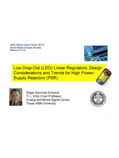
7 Adjust Vi above the start threshold before setting at 15 CHARACTERISTICS (continued)SymbolParameterTest ConditionsUC284 XBUC384 XBUnitMin. Typ. Max. Min. Typ. SECTIONVOLO utput Low LevelISINK = = high LevelISOURCE = = SaturationVCC = 6V; ISINK = TimeTj = 25 C CL = 1nF (2)5015050150nstfFall TimeTj = 25 C CL = 1nF (2)5015050150nsUNDER-VOLTAGE LOCKOUT SECTIONS tart ThresholdX842 Operating VoltageAfter Turn-onX842 SECTIONM aximum Duty CycleX842B/3B94961009496100%X844B/5B4748 50474850 %Minimum Duty Cycle00%TOTAL STANDBY CURRENTIstStart-up CurrentVi = for UCX843 = 14V for UCX842 Supply CurrentVPIN2 = VPIN3 = 0V12171217mAVizZener VoltageIi = 25mA30363036 VUC2842B/3B/4B/5B - UC3842B/3B/4B/5B4/15 Figure 1: Open Loop Test 1K ERROR 5K ISENSEADJUST100K FVREFViOUTPUTGROUND1W1K D95IN343 high peak currents associated with capacitive loadsnecessitate careful grounding techniques.
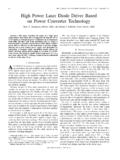
8 Timingand bypass capacitors should be connected closeto pin 5 in a single point ground. The transistor and5 K potentiometer are used to sample the oscillatorwaveform and apply an adjustable ramp to pin (KHz)125102050D95IN333CT=10nFCT=5nFCT=2n FCT=1nFCT=500pFCT=200pFCT=100pFVi=15 VTA=25 CRT(K ) 2: Timing Resistor vs. Oscillator Fre-quency10K20K30K50K100K200K300K500K fOSC(KHz)123510203050%CT=10nFCT=5nFCT=2n FCT=1nFCT=500pFCT=200pFCT=100pFD95IN334V i=15 VTA=25 CFigure 3: Output Dead-Time vs. Oscillator Fre-quencyUC2842 BUC2842B/3B/4B/5B - UC3842B/3B/4B/5B5/15-55-250255075100 TA( C) (mA)D95IN335Vi=15 VVOSC=2 VFigure 4: Oscillator Discharge current vs. (%) (K )D95IN336Vi=15 VCT= CIdischg= 5: Maximum Output Duty Cycle vs. Tim-ing (Hz)-20020406080(dB)180150120906030 D95IN337Vi=15 VVO=2V to 4 VRL=100 KTA=25 CGainPhaseFigure 6: Error Amp Open-Loop Gain andPhase vs.
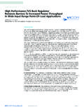
9 (V) (V)D95IN338Vi=15 VTA=-40 CTA=125 CTA=25 CFigure 7: current Sense Input Threshold vs. Er-ror Amp Output 20406080100 Iref(mA)D95IN3390102030405060Vi=15 VTA=-40 CTA=125 CTA=25 CFigure 8: Reference Voltage Change TA( C)D95IN3405060708090100 ISC(mA)Vi=15 VRL Figure 9: Reference Short Circuit current - UC3842B/3B/4B/5B6/150200400600IO(mA)0123 -2-1 Vsat(V)D95IN341Vi=15V80 s Pulsed Load 120Hz RateTA=-40 CTA=25 CViTA=-40 CTA=25 CGNDSink Saturation(Load to Vi)Source Saturation(Load to Ground)Figure 10: Output Saturation Voltagevs. 102030Vi(V)05101520Ii(mA)UCX843/45 UCX842/44RT=10 KCT= CD95IN342 Figure 11: Supply current vs. Supply 12: Output 13: Output Cross Conduction5V REGOSCILLATORPWMCLOCK8456 RTCTGNDOUTPUT7 ViIDCTOUTPUTLARGE RT/SMALL CTCTOUTPUTSMALL RT/LARGE CTD95IN344 Figure 14: Oscillator and Output =15 VCL = = 25 C90%10%50ns/DIVVi =30 VCL = 15pFTA = 25 CVOICC100ns/DIV100mA/DIV20V/DIVUC2842B/3 B/4B/5B - UC3842B/3B/4B/5B7/15 Figure 15 : Error Amp +-Figure 16 : Under Voltage COMMANDTO REST OF IC7< <17mAICCVCCVOFFVOND95IN346 Figure 17 : current Sense Circuit.
10 current (is) is determined by the VIS max RSA small RC filter may be required to suppress switch UVLO, the Output is lowUC2842B/3B/4B/5B - UC3842B/3B/4B/5B8/15 Figure 18 : Slope Compensation 19 : Isolated MOSFET Drive and current Transformer +-+-QSR+-3 RRSNSCVinQ1 NPVGS Waveforms+0+0--50% DC25% DCIpk =V(pin 1) ()UC3842 BUC3842 BUC2842B/3B/4B/5B - UC3842B/3B/4B/5B9/15 Figure 20 : Latched +-EAR+OSC2N39052N39031mARR2R1284 SCR must be selected for a holding current of less than at TA(min).The simple two transistor circuit can be used in place of the SCR as shown. All resistors are +-EARi+1mARdR2R5 CfRf12 From +-EARP+1mARdR2R5 CfRf12 From Amp compensation circuit for stabilizing any current -mode topology exceptfor boost and flyback converters operating with continuous inductor Amp compensation circuit for stabilizing current -mode boost and flybacktopologies operating with continuous inductor 21: Error Amplifier CompensationUC2842B/3B/4B/5B - UC3842B/3B/4B/5B10/15D95IN353+-+RA17f =RBIASOSCC6 VREFRRB+-+-EAR2 RRSQ845235K5K5 KNE55584215TO (RA + 2RB)CDmax =RBRA + 2 RBFigure 23: External Duty Cycle Clamp and Multi Unit +-EA+R2R5RT12 EXTERNALSYNC INPUTThe diode clamp is required if the Sync amplitude is large enough to causethe bottom side of CT to go more than 300mV below F47 48 VREFRF igure 22.