Transcription of INSTALLATION INSTRUCTIONS MOUNTING KIT …
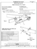
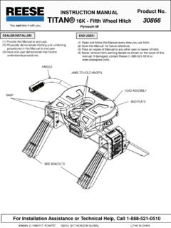
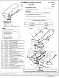
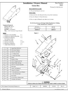
1 30126N 05/23/14 REV F PCN3694 2011, 2014 CEQUENT PERFORMANCE PRODUCTS, INC. PRINTED IN MEXICO INSTALLATION INSTRUCTIONS MOUNTING KIT FORD F250/F350/F450 HD/SD 6 and 8 Beds For Customer Support Call 1-888-521-0510 (1) Provide this Manual to end user. (2) Physically demonstrate procedures in this Manual to end user. (3) Have end user demonstrate that he/she understands procedures. (1) Read and follow this Manual every time you use Hitch. (2) Save this Manual for future reference. (3) Pass on copies of Manual to any other user or owner of Hitch. DEALER/INSTALLER: END USER: Figure 1 Front of vehicle DO NOT EXCEED VEHICLE MANUFACTURER S RATING FOR FIFTH WHEEL TOWING OR MAXIMUM GROSS TRAILER WEIGHT OF 25,000lb. / 11,340kg AND A MAXIMUM KING PIN WEIGHT OF 6,250lb. / 2,835kg. *Please read and understand these INSTRUCTIONS prior to INSTALLATION . PART NUMBER 30126 PART QTY. RAIL (2) BRACKET (DRIVERS SIDE) (1) BRACKET (PASSENGER SIDE) (1) PLUG (4) x 1-3/4 BUTTON HEAD SCREW (4) LOCK WASHER (4) (4) RING (4) GRADE 8 HEXHEAD NUT (4) X X 45 BOLT (4) CONNICAL WASHER (12) , M14 X FLANGE (4) x 1-3/4 GRADE 8 HEX HEAD BOLT (4) 14.
2 Torx T50 IP BIT (1) 30126N 05/23/14 REV F PCN3694 2011, 2014 CEQUENT PERFORMANCE PRODUCTS, INC. PRINTED IN MEXICO 2 FACTORY TRAILER + FULL LIQUID AND GAS TANKS + CARGO, ETC. = GROSS TRAILER WEIGHT Enter total below Figure 2 15-25% GROSS TRAILER WEIGHT (PIN WEIGHT) 75-85% GROSS TRAILER WEIGHT Figure 3 GUIDELINES FOR MATCHING HITCH TRUCK AND TRAILER WARNING: Failure to follow all of these INSTRUCTIONS may result in death or serious injury! INDEX WARNING: Failure to check and follow tow ratings could result in tow vehicle damage or truck and trailer separation while towing. Trailer and its contents together must not exceed truck, hitch and/or trailer tow ratings. Towing vehicle must have a manufacturer s rated towing capacity equal to or greater than the gross trailer weight (dry weight of the trailer plus payload of the trailer). (Figure 2) Gross weight of trailer must not exceed fifth wheel hitch rating.
3 King pin weight must not exceed fifth wheel rating (Figure 3). If in doubt have king pin weight measured by a qualified technician. 1. Maximum Gross Trailer Weight of : 25,000 lb / 11,340kg. Vehicle tow rating: _____. Total calculated Gross Trailer Weight (Figure 2):_____. *Trailer weight should be the lowest of these recorded ratings for safe towing conditions. 2. Cequent Performance Products, Inc. hitches are designed for use with recreational fifth wheel trailers only. Hitch applications other than recreational fifth wheel trailers must be approved in writing by the Cequent Performance Products, Inc. Engineering Department. 3. Use only a SAE 2-inch kingpin with your REESE Elite Series Fifth Wheel Hitch. 4. Approximately 15%-25% of trailer weight should be on hitch (Pin Weight)(Figure 3). 1. GUIDELINES FOR MATCHING TOW VEHICLE AND TRAILER P. 2-4 2. ASSEMBLY INSTRUCTIONS P. 5-9 3. CEQUENT PERFORMANCE PRODUCTS, INC.
4 LIFETIME LIMITED WARRANTY P. 10 30126N 05/23/14 REV F PCN3694 2011, 2014 CEQUENT PERFORMANCE PRODUCTS, INC. PRINTED IN MEXICO 3 5. Trucks come in many different configurations. Cequent Performance Products, Inc. hitches are designed for use in light trucks such as the Ford F-Series, the Chevy Silverado and the Dodge Ram. Cequent Performance Products, Inc. recommends the use of light trucks with beds 6ft. long or longer for the best combination in truck - trailer turning clearance. See website for vehicle application. NOTE: To prevent the trailer from hitting the cab with the trailer turned 90 , the center of the hitch should be at least 52in. from the back of the cab when using a long bed truck. (Actual distance required will depend on trailer width and king pin location.) Short bed (Minimum 38in. from back cab to axle center line) trucks require a minimum of 13in. extended pin box (Figure 5) or a SIDEWINDERTM Pin box or slider hitch assembly for regular maneuvers.
5 6. The height of the hitch and the pin box should be adjusted so the trailer is approximately level as it is towed. Allow approximately 6 in. - 9 in. clearance between the top of the bed rails and the underside of the front of the trailer for pitch and roll of the trailer. (Figure 6). Allow more clearance between pickup walls and trailer for off road use. KING PIN RV TRAILER TRUCK Figure 4 Conventional Pin Box Extended Pin Box Figure 5 Rule of thumb: The distance from the back of the truck cab to the center of the rear truck axle ( X in Figure 4), should be approximately 4 in. greater than one-half the trailer width ( Y in Figure 4) Approximately 6-9 in. Level Trailer Figure 6 WARNING: Do Not install this fifth wheel hitch on or attempt to tow with a short bed pickup truck that has a bed shorter than 6 ft. unless trailer is equipped with a SidewinderTM pin box! CAUTION: The measurements above are guidelines.
6 If your measurements are close to these numbers re-check clearances. If vehicle and/or trailer has any added bed vicinity accessories ( fairings, air dams, ground effects, bed rails, fuel-cells, toolbox, etc.), additional dimensioning and clearance checks have to be made. 30126N 05/23/14 REV F PCN3694 2011, 2014 CEQUENT PERFORMANCE PRODUCTS, INC. PRINTED IN MEXICO 4 B D C A *MEASURED WITH TRAILER LEVEL, ON LEVEL GROUND WARNING: Connection for trailer wiring must be located at the side of the truck bed between the driver s seat and the rear wheel to prevent operators from working between the truck and trailer. Avoid putting any part of your body under the trailer or between the truck and trailer. Unexpected or accidental movement of the truck or the trailer can cause serious injury or death If you must place any part of your body under the trailer or between the truck and trailer you MUST perform ALL of the following steps: Check that the truck transmission is in park Check that the emergency brake is on Block in front of and behind all trailer tires Check that the trailer landing gear are resting on firm ground 8.
7 If a lube plate is to be used with a REESE Elite Fifth Wheel it must be at least 12 in diameter. Cequent Performance Products, Inc. offers this optional lube plate as part # 83001. Figure 7 7. Hitch height determination: With trailer leveled and on level ground measure from the ground to the bottom of the king pin box ( A in Figure 7). Secondly measure the height of the inside of the truck bed to the ground ( B in Figure 7). Determine the amount of clearance over the side rails ( C and D in Figure 7). Hitch Height = A B + 2 ** ** The 2 value is an estimate of suspension compression due to king pin weight of the trailer. This compression could range between 1 -5 depending on the truck being used and the trailer being towed. D C + 2 > 6 30126N 05/23/14 REV F PCN3694 2011, 2014 CEQUENT PERFORMANCE PRODUCTS, INC. PRINTED IN MEXICO 5 9. The following INSTRUCTIONS should be used to mount the fifth wheel MOUNTING kit.
8 Care and attention to detail will ensure a quick quality INSTALLATION . Check parts against parts list to become familiar with parts in kit. (Figure 1) 10. If extra clearance is needed to install the frame brackets, raise the rear of the truck high enough to allow the rear tires to hang down freely. This will provide the maximum room to install the fifth wheel brackets. 11. Remove plastic bed liner if applicable. Plastic drop-in bed liners will be cut later. (See Figure 15) Spray-in bed liners and bed mats less than 1/4 thick will work with normal INSTALLATION INSTRUCTIONS . Note: Consult installer for recommended curing time on spray-in liner before cutting holes through bed. 12. Use only CEQUENT PERFORMANCE PRODUCTS, Inc. supplied bolts, nuts, and washers to install this kit. All bolts and nuts are Grade 8 unless specified otherwise. 13. These INSTRUCTIONS are intended for 2011 Ford Super Duty with 6 to 8 foot bed.
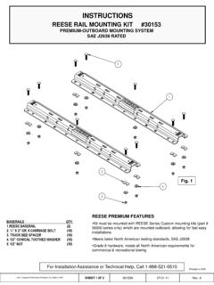
9 Each frame bracket must be bolted to the vehicle frame with two bolts. GENERAL INSTRUCTIONS FOR FIFTH WHEEL INSTALLATION TOOLS 1/8" Drill Bit 15/16" Socket & Open End Wrench Torx T50IP Bit (Supplied with Kit) 200 lb-ft Torque Wrench Rubber Mallet 2-3/4 Hole Saw 21mm Socket or Open End Wrench 19mm Socket or Open End Wrench 1/2 Drive Swivel Head Ratchet 3/8 Allen Wrench Socket CAUTION! Read pages 2-4 of these INSTRUCTIONS before starting INSTALLATION . Failure to do so could result in significant vehicle damage! WARNING: If the truck is raised, be sure that the truck is properly blocked and restrained to prevent the truck from falling. Failure to do so may result in the truck suddenly falling, causing death or serious injury. CAUTION: Check for obstructions before drilling. Failure to do so could result in damaged fuel or brake lines, structural members, etc. CEQUENT PERFORMANCE PRODUCTS, Inc. does its best to communicate tow vehicle manufacturer changes; however, it is ultimately the responsibility of the installer to prevent damage due to INSTALLATION .
10 CAUTION: These INSTRUCTIONS are guidelines only. Actual INSTALLATION is the responsibility of the installer and the owner. Always measure truck and trailer before installing hitch to be sure that there is clearance at the cab and at the bumper to allow for turns. 1/8 pilot holes in truck bed at outer dimpled locations (approximate dimensions of Figure 15). The middle dimple is for the goose ball only. (See gooseneck INSTRUCTIONS if applicable.) These dimpled locations are placed by the factory. If dimples are not present, refer to (Figure 15) located on page 9. Use a 2 hole saw to cut hole at pilot holes. Note: Consult installer for recommended curing time on spray in liner before cutting holes through bed. Optional: Spray under coating around 2 holes to prevent rusting. 15. Locate the area where the base rails will be inserted above the rear wheel on the passengers side. There are two hat channels supporting the truck bed over the rear wheel.