Transcription of Instruction Leaet IL02602013E Rev D Effective September ...
1 Table of Introduction Assembly Drawing Installation Certifications and Electromagnetic Compatibility Testing Universal Resistance Temperature Detector (URTD) Module IIInstruction Leaflet IL02602013E Rev D Effective September IntroductionThe Universal RTD Module II (URTDII) is an electronic resistance-temperature detector accessory for the devices shown in Table 1:Table 1, Applicable DevicesLegacyExpandedMP3000 EMR3000MP4000 EMR4000FP6000 EMR5000IQ1000 IIETR4000 ETR5000 EGR4000 EGR5000 The URTDII can be used to monitor as many as 12 RTD inputs, These inputs fall into four groups that consist of: six motor windings, two motor bearings, two load bearings, and two auxiliary RTDs. The URTDII can be programmed to accept any of the follow-ing types of RTD inputs: 100 ohm platinum 100 ohm nickel 120 ohm nickel 10 ohm copperThe RTD type can be selected for each of the four RTD groups.
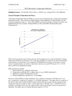
2 For example, The motor winding RTD inputs can be programmed for 10 ohm copper and the motor bearing RTD inputs can be programmed for 120 ohm nickel. The URTDII can transmit its information to a protective device using a fiber optic link. It can be mounted remotely up to 122 meters (400 feet) from the protective device when using the fiber optic link. The URTDII can also be used as a stand-alone device that communicates on a Modbus network. A bidirectional RS485 port is provided on the bottom of the unit. 2IL02602013E Rev D Universal Resistance Temperature September 2013 Detector (URTD) Module II IL02602013E Rev D - September 2013 - Figure 1, Dimension Drawing Assembly Drawing The URTDII dimensions are shown in Figure1. J2J10 BRTD7C/MB1C21 RTD7+/MB1+20 RTD7-/MB1-19 Shield18 RTD8C/MB2C17 RTD8+/MB2+16 RTD8-/MB2-15 RTD9C/LB1C14 RTD9+/LB1+13 RTD9-/LB1-12 Shield11 RTD10C/LB2C10 RTD10+/LB2+9 RTD10-/LB2-8 RTD11C/AUX1C7 RTD11+/AUX1+6 RTD11-/AUX1-5 Shield4 RTD12C/AUX2C3 RTD12+/AUX2+RTD12-/AUX2-21 PWR IN 2 PWR IN 121123456789101112131415161718192021RS-4 85 MODBUSFIBEROPTICS2S1 UNIVERSAL RTD MODULEURTD-IIBACOMS hield1234J110N1120N18J10 ARTD6C/MW6 CRTD6+/MW6+RTD6-/MW6-ShieldRTD5C/MW5 CRTD5+/MW5+RTD5-/MW5-RTD4C/MW4/CRTD4+/MW 4+RTD4-/MW4-ShieldRTD3C/MW3 CRTD3+/MW3+RTD3-/MW3-RTD2C/MW2 CRTD2+/MW2+RTD2-/MW2-ShieldRTD1C/MW1 CRTD1+/MW1+RTD1- [ ].
3 20 [ ] [ ] [ ].20 [ ] [ ]Style No.: Cat No. : Serial No.: Universal RTD Module : [ ] [ ]MTGMTG212019181716151413121110987654321 213 Universal Resistance Temperature IL02602013E Rev D Detector (URTD) Module II September 2013 IL02602013E Rev D - September 2013 - Installation WARNINGHAZARDOUS CONDITIONS MAY RESULT IF THIS PROD-UCT IS NOT USED FOR INTENDED PURPOSES. THE DEVICE WILL NOT OPERATE PROPERLY IF USED IN A MANNER NOT SPECIFIED BY THE MANUFACTURER. This industrial type control should be installed, operated and maintained by adequately trained personnel. The instruc-tions in this document do not cover all details, variations, or combinations of the equipment, its storage, delivery, installation, check-out, safe operation, or maintenance.
4 Care must be exercised to comply with local, state, and national regulations, as well as safety practices, for this class of MountingThe URTDII can be mounted to the back of a MP3000 or MP4000 using the supplied bracket and hardware. The URTDII can also be mounted as a stand-alone device at a convenient location using the mounting dimensions pro-vided in Figure 1. Device must be located where hazardous terminals are not accessible. Control PowerConnect the power supply terminals (labeled J10A) on the URTDII to a suitable power source. Refer to Table 4 for con-nection guidelines. The terminal blocks used in this device are suitable for field wiring, No. 22-14 AWG, solid or strand-ed copper wire conductor, tightening torque 7 in. lb. The power supply wiring should be fused or put on a break-er sized to protect the wire. A circuit breaker shall be included in the building circuit breaker shall be in close proximity to the equip-ment and within easy reach of the operator.
5 The circuit breaker shall be marked as the disconnecting device for the equipment. Product shall be installed in accordance with local codes. Table 3, IEC Symbol Description IEC Symbol Description Both Direct and Alternating CurrentDirect Current Equipment protected throughout by DOUBLE INSULATION or REINFORCED INSULATIONTo Power Supply Terminal Block Power (J10A)AC Power SupplyDC Power Supply 1 Line Positive 2 Neutral NegativeTable 4, URTDII Power Connections Table 2, SpecificationsSpecifications URTDII-01 URTDII-02 Input Power Requirements48-240 VAC / 48-250 VDC24-48 VDCF requency 50/60 Hz or DCDCP ower WOperating Temperature-20 to 55 C (-4 to 131 F)-20 to 55 C (-4 to 131 F)Storage Temperature -40 to 85 C (-40 to 185 F)-40 to 85 C (-40 to 185 F)
6 Humidity 0 to 95% Non-condensing 0 to 95% Non-condensing Altitude2000 Meters2000 MetersPollution Degree22 Installation CategoryII4IL02602013E Rev D Universal Resistance Temperature September 2013 Detector (URTD) Module II IL02602013E Rev D - September 2013 - URTDII WiringEach RTD must be wired to the URTDII, as shown in Figures 2 and 3. The following guidelines must be observed:Use only one type of RTD (10 ohm copper, 100 ohm nickel, 100 ohm platinum , or 120 ohm nickel) for each RTD group: motor winding, motor bearing, load bearing and auxiliary. For example, you cannot monitor one 10 ohm copper motor bearing RTD and one 120 ohm nickel motor bearing RTD. However, you can monitor 10 ohm copper winding RTDs and 100 ohm nickel motor bearing Use #18 three-conductor, stranded, twisted, copper wire to connect the RTD to the URTDII.
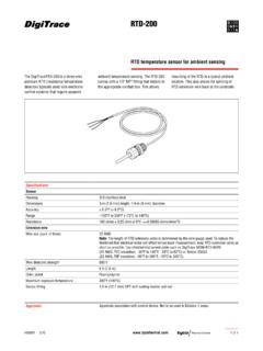
7 2. Connect three conductors from the RTD to the URTDII. (Two return wires must be connected together). Where the motor has only two leads from the RTD, connect two of the three conductors together at one of the leads. Make this connection as close to the RTD as possible (see Figure 3). If only two conductors are connected between the RTD and the URTDII, the device will not operate Connect the cable shield and drain wires to the appropri-ate terminal on the URTDII. At the opposite end, cut the shield and drain wire short and tape them, to prevent short circuits. otee:NDo not connect this wiring at the RTD If one or more of the 12 possible RTD inputs on the module are not used, they can be left open or jumpered out without affecting the operation of the protective +3C4S5-6+7C8-9+10C11S12-13+14C15-16+17C1 8S19-20+21C21201918171615141312111098765 4321C+-SC+-C+-SC+-C+-SC+-J10BJ2 AuxiliaryLoadBearingsMotorBearingsMotorW indingsRTDRTDRTDRTDRTDRTDRTDRTDRTDRTDRTD RTDU niversalRTD Module IIWireShield/DrainTerminalsMotorUSE TAPE TO INSULATEDO NOT CONNECT CABLE'S SHIELD WIRE AT THIS END!
8 TerminalsMotorWireShield/DrainWireShield /DrainWireShield/DrainWireShield/DrainWi reShield/DrainNCotee:N1. Each shielded cable conductor must be connected on the URTDII as Use of three-lead RTDs is RTDs must not be grounded at the motor, and no common connections between RTDs should be made at the A suitable earth ground should be connected to J10B-4, J10B-11, J-10B-18, J2-4, J2-11, or J2-18. It is recommended that a ground connection is made to both sides of the unit. Figure 2, RTD Wiring (Three-Lead Type)5 Universal Resistance Temperature IL02602013E Rev D Detector (URTD) Module II September 2013 IL02602013E Rev D - September 2013 - 4321SC+-RTDWireShield/DrainRTD WIRING (THREE-LEAD TYPE)4321SC+-RTDUSE TAPE TO INSULATECABLE'S SHIELD WIRE AT THIS END!
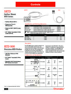
9 RTD WIRING (TWO-LEAD TYPE)TerminalsMotorDO NOT CONNECTT erminalsMotorUSE TAPE TO INSULATECABLE'S SHIELD WIRE AT THIS END!DO NOT CONNECTWireShield/DrainNotes:1. Connect cable shield at URTDII terminals only. Cut shield short at motor end and use shrink tubing or electrical tape to RTDs must not be grounded at the motor and no common connections between individual RTDs should be made at the 3, Wiring to URTDII6IL02602013E Rev D Universal Resistance Temperature September 2013 Detector (URTD) Module II IL02602013E Rev D - September 2013 - Figure 4, DIP Switches S2 Figure 5, DIP Switch PositionsA. Motor Winding RTDC. Load Bearing RTDRTD Type Switch Settings RTD Type Switch Settings1256100 Ohm platinum ONON100 Ohm platinum ONON100 Ohm Nickel OFFON100 Ohm Nickel OFFON120 Ohm Nickel ONOFF120 Ohm Nickel ONOFF10 Ohm CopperOFFOFF10 Ohm CopperOFFOFFB.
10 Motor Bearing RTDD. Auxiliary RTDRTD TypeSwitch SettingsRTD TypeSwitch Settings3478100 Ohm platinum ONON100 Ohm platinum ONON100 Ohm Nickel OFFON100 Ohm Nickel OFFON120 Ohm Nickel ONOFF120 Ohm Nickel ONOFF10 Ohm CopperOFFOFF10 Ohm CopperOFFOFFT able 5, DIP Switch Settings AuxiliaryRTD TypeLoad BearingRTD TypeMotor BearingRTD TypeMotor WindngRTD Programming the Universal RTD Module IIThe URTDII must be programmed for the type of RTDs that are being monitored. A DIP switch assembly on the module enables programming for the specific application. Figure 4 shows the arrangement of the DIP switches in the assem-bly. They provide four selection groupings that you must set during Figure 4 shows, the DIP switch assembly contains eight two-position slide switches that are set in combination. Each switch is set to ON or OFF by sliding it back and facing the DIP switches, slide them: Toward the FRONT of the unit for the ON position, and Toward the REAR of the unit for the OFF the ON and OFF designations on the DIP switches shown in Figures 4 and :NAlways look for the ON and OFF designations on the hardware or printed circuit board to be sure you are setting the switches switch ON and OFF settings are shown in Table 5.