Transcription of Introduction to Finite Element Analysis in Solid Mechanics
1 1 Chapter 2 Introduction to Finite Element Analysis in Solid Mechanics Most practical design calculations involve components with a complicated three-dimensional geometry, and may also need to account for inherently nonlinear phenomena such as contact, large shape changes, or nonlinear material behavior. These problems can only be solved using computer simulations. The Finite Element method is by far the most widely used and versatile technique for simulating deformable solids. This chapter gives a brief overview of the Finite Element method, with a view to providing the background needed to run simple simulations using a commercial Finite Element program.
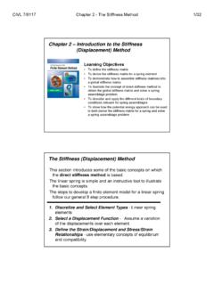
2 More advanced Analysis requires a deeper understanding of the theory and implementation of Finite Element codes, which will be addressed in the next chapter. HEALTH WARNING: It is deceptively easy to use commercial Finite Element software: most programs come with a nice user-interface that allows you to define the geometry of the Solid , choose a material model, generate a Finite Element mesh and apply loads to the Solid with a few mouse clicks. If all goes well, the program will magically turn out animations showing the deformation; contours showing stress distributions; and much more besides. It is all too easy, however, to produce meaningless results, by attempting to solve a problem that does not have a well defined solution; by using an inappropriate numerical scheme; or simply using incorrect settings for internal tolerances in the code.
3 In addition, even high quality software can contain bugs. Always treat the results of a Finite Element computations with skepticism! Introduction The Finite Element method (FEM) is a computer technique for solving partial differential equations. One application is to predict the deformation and stress fields within Solid bodies subjected to external forces. However, FEM can also be used to solve problems involving fluid flow, heat transfer, electromagnetic fields, diffusion, and many other phenomena. The principle objective of the displacement based Finite Element method is to compute the displacement field within a Solid subjected to external forces.
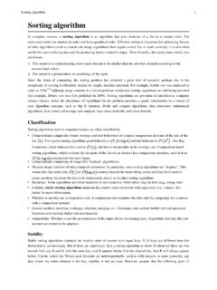
4 To make this precise, visualize a Solid deforming under external loads. Every point in the Solid moves as the load is applied. The displacement vector u(x) specifies the motion of the point at position x in the undeformed Solid . Our objective is to determine u(x). Once u(x) is known, the strain and stress fields in the Solid can be deduced. xu(x)e3e1e2 OriginalConfigurationDeformedConfigurati ony 2 There are two general types of Finite Element Analysis in Solid mechancis. In most cases, we are interested in determining the behavior of a Solid body that is in static equilibrium. This means that both external and internal forces acting on the Solid sum to zero.
5 In some cases, we may be interested in the dynamic behavior of a Solid body. Examples include modeling vibrations in structures, problems involving wave propagation, explosive loading and crash Analysis . For Dynamic Problems the Finite Element method solves the equations of motion for a continuum essentially a more complicated version of m Fa. Naturally, in this case it must calculate the motion of the Solid as a function of time. For Static Problems the Finite Element method solves the equilibrium equations F0. In this case, it may not be necessary to calculate the time variation of motion. However, some materials are history dependent ( metals deformed in the plastic regime).
6 In addition, a static equilibrium problem may have more than one solution, depending on the load history. In this case the time variation of the solution must be computed. For some applications, you may also need to solve additional field equations. For example, you may be interested in calculating the temperature distribution in the Solid , or calculating electric or magnetic fields. In addition, special Finite Element procedures are available to calculate buckling loads and their modes, as well as natural frequencies of vibration and the corresponding mode shapes for a deformable Solid . To set up a Finite Element calculation, you will need to specify 1. The geometry of the Solid .
7 This is done by generating a Finite Element mesh for the Solid . The mesh can usually be generated automatically from a CAD representation of the Solid . 2. The properties of the material. This is done by specifying a constitutive law for the Solid . 3. The nature of the loading applied to the Solid . This is done by specifying the boundary conditions for the problem. 4. If your Analysis involves contact between two more more solids, you will need to specify the surfaces that are likely to come into contact, and the properties ( friction coefficient) of the contact. 5. For a dynamic Analysis , it is necessary to specify initial conditions for the problem. This is not necessary for a static Analysis .
8 6. For problems involving additional fields, you may need to specify initial values for these field variables ( you would need to specify the initial temperature distribution in a thermal Analysis ). You will also need to specify some additional aspects of the problem you are solving and the solution procedure to be used: 1. You will need to specify whether the computation should take into account Finite changes in the geometry of the Solid . 2. For a dynamic Analysis , you will need to specify the time period of the Analysis (or the number of time increments) 3. For a static Analysis you will need to decide whether the problem is linear, or nonlinear. Linear problems are very easy to solve.
9 Nonlinear problems may need special procedures. 4. For a static Analysis with history dependent materials you will need to specify the time period of the Analysis , and the time step size (or number of steps) 5. If you are interested in calculating natural frequencies and mode shapes for the system, you must specify how many modes to extract. 6. Finally, you will need to specify what the Finite Element method must compute. The steps in running a Finite Element computation are discussed in more detail in the following sections. 3 The Finite Element Mesh for a 2D or 3D component The Finite Element mesh is used to specify the geometry of the Solid , and is also used to describe the displacement field within the Solid .
10 A typical mesh (generated in the commercial FEA code ABAQUS) is shown in the picture to the right. A Finite Element mesh may be three dimensional, like the example shown. Two dimensional Finite Element meshes are also used to model simpler modes of deformation. There are three main types of two dimensional Finite Element mesh: 1. Plane stress 2. Plane strain 3. Axisymmetric In addition, special types of Finite Element can be used to model the overall behavior of a 3D Solid , without needing to solve for the full 3D fields inside the Solid . Examples are shell elements ; plate elements ; beam elements and truss elements . These will be discussed in a separate section below.