Transcription of Introduction to Semiconductor Technology ...
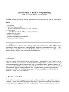
1 AN900/11001/15AN900 APPLICATION NOTEINTRODUCTION TO Semiconductor TECHNOLOGYby Microcontroller Division ApplicationsINTRODUCTIONAn integrated circuit is a small but sophisticated device implementing several electronic func-tions. It is made up of two major parts: a tiny and very fragile silicon chip (die) and a packagewhich is intended to protect the internal silicon chip and to provide users with a practical wayof handling the component. This note describes the various front-end and back-end manu-facturing processes and takes the transistor as an example, because it uses the MOS tech-nology. Actually, this Technology is used for the majority of the ICs manufactured at TO Semiconductor TECHNOLOGY1 THE FABRICATION OF A Semiconductor DEVICEThe manufacturing phase of an integrated circuit can be divided into two steps.
2 The first,wafer fabrication, is the extremely sophisticated and intricate process of manufacturing thesilicon chip. The second, assembly, is the highly precise and automated process of pack-aging the die. Those two phases are commonly known as Front-End and Back-End . Theyinclude two test steps: wafer probing and final 1. Manufacturing Flow Chart of an Integrated WAFER FABRICATION (FRONT-END)Identical integrated circuits, called die, are made on each wafer in a multi-step process. Eachstep adds a new layer to the wafer or modifies the existing one. These layers form the ele-ments of the individual electronic main steps for the fabrication of a die are summarized in the following table.
3 Some ofthem are repeated several times at different stages of the process. The order given heredoesn't reflect the real order of fabrication step shapes the different components. The principle is quite simple (see draw-ing on next page). Resin is put down on the wafer which is then exposed to light through a specific mask. The lighten part of the resin softens and is rinsed off with solvents (developing step).EtchingThis operation removes a thin film material. There are two different methods: wet (using a liquid or soluble compound) or dry (using a gaseous compound like oxygen or chlorine).DiffusionThis step is used to introduce dopants inside the material or to grow a thin oxide layer onto the wafer.
4 Wafers are inserted into a high temperature furnace (up to 1200 C) and doping gazes penetrate the silicon or react with it to grow a silicon oxide ImplantationIt allows to introduce a dopant at a given depth into the material using a high energy electron DepositionIt allows the realization of electrical connections between the different cells of the integrated circuit and the outside. Two different methods are used to deposit the metal: evaporation or sputtering."Front-End""Back-End"WAFERFAB RICATIONASSEMBLYW aferFinalTestProbingVR02103A23/15 Introduction TO Semiconductor TECHNOLOGYI nitially, the silicon chip forms part of a very thin (usually 650 microns), round silicon slice: theraw wafer.
5 Wafer diameters are typically 125, 150 or 200 mm (5, 6 or 8 inches). However rawpure silicon has a main electrical property: it is an isolating material. So some of the featuresof silicon have to be altered, by means of well controlled processes. This is obtained by"doping" the silicon. Dopants (or doping atoms) are purposely inserted in the silicon lattice, hence changing thefeatures of the material in predefined areas: they are divided into N and P categories rep-resenting the negative and positive carriers they hold. Many different dopants are used toachieve these desired features: Phosphorous, Arsenic (N type) and Boron (P type) are themost frequently used ones.
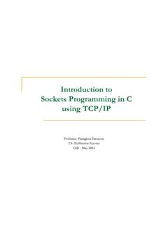
6 Semiconductors manufacturers purchase wafers predoped with Nor P impurities to an impurity level ppm (one doping atom per ten million atoms of silicon).There are two ways to dope the silicon. The first one is to insert the wafer into a gases are then introduced which impregnate the silicon surface. This is one part of themanufacturing process called diffusion (the other part being the oxide growth). The secondway to dope the silicon is called ionic implantation. In this case, doping atoms are introducedinside the silicon using an electron beam. Unlike diffusion, ionic implantation allows to putatoms at a given depth inside the silicon and basically allows a better control of all the mainparameters during the process.
7 Ionic implantation process is simpler than diffusion processbut more costly (ionic implanters are very expensive machines).PassivationWafers are sealed with a passivation layer to prevent the device from contamina-tion or moisture attack. This layer is usually made of silicon nitride or a silicon oxide s the last step of wafer fabrication. Wafer thickness is reduced (for microcontroller chips, thickness is reduced from 650 to 380 microns), and sometimes a thin gold layer is deposited on the back of the TO Semiconductor TECHNOLOGYF igure 2. Diffusion and Ionic Implantation ProcessesPhotomasking (or masking) is an operation that is repeated many times during the operation is described on the above graph.
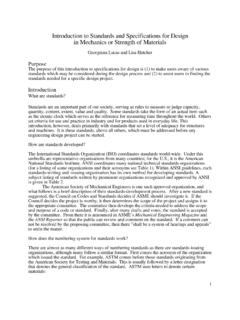
8 This step is called photomasking because thewafer is masked in some areas (using a specific pattern), in the same way one masks out or protects the windscreens of a car before painting the body. But even if the process is some-what similar to the painting of a car body, in the case of a silicon chip the dimensions aremeasured in tenth of microns. The photoresist will replicate this pattern on the wafer. The ex-posed part of the photoresist is then rinsed off with a solvent (usually hydrofluoric or phos-phoric acid).Figure 3. Photomasking ProcessVR02103 BDIFFUSION PROCESSIONIC IMPLANTATIONIONIC IMPLANTERE lectron BeamHIGH TEMPERATUREDIFFUSION FURNACED oping atomsPROCESSOXIDE GROWTHDOPINGDOPINGSiO2 Oxygen (O )2 VACUUM5/15 Introduction TO Semiconductor TECHNOLOGYM etal deposition is used to put down a metal layer on the wafer surface.
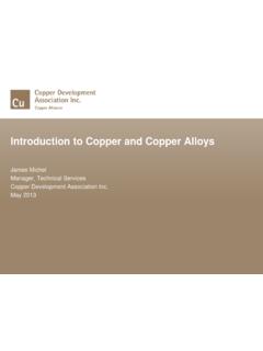
9 There are two waysto do that. The process shown on the graph below is called sputtering. It consists first in cre-ating a plasma with argon ions. These ions bump into the target surface (composed of a metal,usually aluminium) and rip metal atoms from the target. Then, atoms are projected in all the di-rections and most of them condense on the substrate surface. Figure 4. Metal Deposition ProcessEtching process is used to etch into a specific layer the circuit pattern that has been definedduring the photomasking process. Etching process usually occurs after deposition of the layerthat has to be etched. For instance, the poly gates of a transistor are obtained by etching thepoly layer.
10 A second example are the aluminium connections obtained after etching of the alu-minium 5. Etching ProcessVR02103 CPLASMASUBSTRATEPOWER SUPPLYThin Metal LayerCATHODEANODEMETALATOMSVR02103 DPhotoresist MaskThin Film to be etchedSubstrateBEFOREAFTER6/15 Introduction TO Semiconductor TECHNOLOGYP hotomasking, ionic implantation, diffusion, metal deposition, and etching processesare repeated many times, using different materials and dopants at different temperatures inorder to achieve all the operations needed to produce the requested characteristics of the sil-icon chip. The resolution limit (minimal line size inside the circuit) of current Technology is Achieving such results requires very sophisticated processes as well as superiorquality is the final step of wafer fabrication.