Transcription of Isolated, Synchronous Forward Controller with Active Clamp ...
1 Isolated, Synchronous Forward Controller with Active Clamp and iCoupler Data Sheet ADP1074 Rev. D Document Feedback Information furnished by Analog Devices is believed to be accurate and reliable. However, no responsibility is assumed by Analog Devices for its use, nor for any infringements of patents or other rights of third parties that may result from its use. Specifications subject to change without notice. No license is granted by implication or otherwise under any patent or patent rights of Analog Devices. Trademarks and registered trademarks are the property of their respective owners. One Technology Way, Box 9106, Norwood, MA 02062-9106, : 2017 2020 Analog Devices, Inc.
2 All rights reserved. Technical Support FEATURES Current mode Controller for Active Clamp Forward topology Integrated 5 kV (wide body SOIC package) or kV (LGA package) rated dielectric isolation voltage with Analog Devices, Inc., patented iCoupler technology Wide voltage supply range Primary VIN: up to 60 V Secondary VDD2: up to 36 V Integrated 1 A primary side MOSFET driver for power switch and Active Clamp reset switch Integrated 1 A secondary side MOSFET drivers for Synchronous rectification Integrated error amplifier and <1% accurate reference voltage Programmable slope compensation Programmable frequency range: 50 kHz to 600 kHz typical Frequency synchronization Programmable maximum duty cycle limit Programmable soft start Smooth soft start from precharged load Programmable dead time power saving light load mode using MODE pin Protection features such as short circuit, output overvoltage, and overtemperature protection Cycle-by-cycle input overcurrent protection Precision enable UVLO with hysteresis PGOOD pin for system flagging Tracking function from secondary side Remote (secondary side) shutdown/reset function Safety and regulatory approvals (pending) UL recognition 5000 V rms for 1 minute per UL 1577 (for wide body SOIC package)
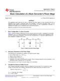
3 3000 V rms for 1 minute per UL 1577 (for LGA package) CSA component acceptance notice 5A VDE certificate of conformity DIN V VDE V 0884-10 (VDE V 0884-10):2006-12 VIORM = 849 V peak (for wide body SOIC package) VIORM = 560 V peak (for LGA package) CQC certification per Available in 24-lead SOIC_W package and 24-terminal LGA package AEC-Q100 Qualified for Automotive Applications APPLICATIONS Isolated dc-to-dc power conversion Intermediate bus voltage generation Telecom, industrial Base station and antenna RF power Small cell PoE powered device Enterprise switches/routers Core/edge/metro/optical routing power modules SIMPLIFIED BLOCK DIAGRAM Active CLAMPFORWARDBIASWDG12 VDC/8 AINPUTSYNCHRONOUSRECTIFIEROPTIONALSTART- UPCIRCUITRYADP107415627-001 Figure 1.
4 ADP1074 Data Sheet Rev. D | Page 2 of 32 TABLE OF CONTENTS Features .. 1 Applications .. 1 Simplified Block Diagram .. 1 Revision History .. 2 General Description .. 3 Specifications .. 4 Insulation and Safety Related Specifications .. 7 Regulatory Information .. 8 DIN V VDE V 0884-10 (VDE V 0884-10) Insulation Characteristics .. 9 DIN V VDE V 0884-10 (VDE V 0884-10) Insulation Characteristics .. 10 Absolute Maximum Ratings .. 11 Thermal Resistance .. 11 ESD 11 Pin Configurations and Function Descriptions .. 12 Typical Performance Characteristics .. 14 Theory of Operation .. 16 Detailed Block Diagram .. 17 Primary Side Supply, Input Voltage, and 18 Secondary Side Supply and LDO.
5 18 Precision Enable .. 18 Soft Start Procedure .. 18 Output Voltage Sensing and Feedback .. 19 Loop Compensation and Steady State Operation .. 19 Slope Compensation .. 20 Input/Output Current-Limit Protection .. 20 Temperature Sensing .. 21 Frequency Setting (RT Pin) .. 21 Maximum Duty Cycle .. 21 Frequency Synchronization .. 21 Synchronous rectifier (SR) Drivers .. 22 Output Overvoltage Protection (OVP) .. 22 Active Clamp (PGATE) .. 22 Leading Edge Blanking .. 22 Gate Delay and SR Dead Time .. 22 Light Load Mode (LLM) and SR Phase In .. 22 External Start-Up Circuit .. 23 Soft Stop .. 23 power Good .. 23 OCP/Feedback Recovery .. 24 Output Voltage Tracking.
6 24 Remote System Reset .. 24 OCP Counter .. 26 Insulation Lifetime .. 26 Layout Guidelines .. 27 Typical Application Circuits .. 28 Outline Dimensions .. 31 Ordering Guide .. 31 REVISION HISTORY 6/2020 Rev. C to Rev. D Changes to Ordering Guide .. 31 4/2020 Rev. B to Rev. C Moved General Description Section .. 3 Added Table 1; Renumbered Sequentially .. 3 8/2018 Rev. A to Rev. B Changes to Table 1 .. 3 Changes to Input/Output Current-Limit Protection Section .. 19 8/2018 Rev. 0 to Rev. A Added CC-24-6 Package .. Throughout Changes to Features Section .. 1 Changes to Table 1 .. 3 Changes to Table 2 .. 6 Added Table 4; Renumbered Sequentially.
7 7 Changes to Table 3 .. 7 Added DIN V VDE V 0884-10 (VDE V 0884-10) Insulation Characteristics Section, Table 5, and Figure 2; Renumbered Sequentially .. 8 Added DIN V VDE V 0884-10 (VDE V 0884-10) Insulation Characteristics Section, Table 6, and Figure 3 .. 9 Added Table 10 .. 10 Changes to Table 8 and Table 9 .. 10 Added Figure 5 .. 11 Changes to Input/Output Current Limit Protection Section .. 19 Added Figure 15 .. 20 Updated Outline Dimensions .. 30 Changes to Ordering Guide .. 30 10/2017 Revision 0: Initial Version Data Sheet ADP1074 Rev. D | Page 3 of 32 GENERAL DESCRIPTION The ADP1074 is a current mode, fixed frequency, Active Clamp , Synchronous Forward Controller designed for isolated dc to dc power supplies.
8 Analog Devices proprietary iCouplers are integrated in the ADP1074 to eliminate the bulky signal trans-formers and optocouplers that transmit signals over the isolation boundary. Integrating the iCouplers reduces system design complexity, cost, and component count and improves overall system reliability. With the integrated isolators and metal-oxide semiconductor field effect transistor (MOSFET) drivers on both the primary and the secondary side, the ADP1074 offers a compact system level design and yields a higher efficiency than a non- Synchronous Forward converter at heavy loads. The primary side pins provide functions for programming the switching frequency, maximum duty cycle, external frequency synchronization, and slope compensation.
9 The secondary side pins provide functions for differential output voltage sensing, overvoltage, power good, tracking, and programmable light load mode setting. The feedback signal and timing of Synchronous rectifier pulse-width modulations (PWMs) are transmitted from primary to secondary or from secondary to primary sides through the iCouplers using a proprietary transmission scheme. The ADP1074 also offers features such as input current protection, undervoltage lockout (UVLO), precision enable with adjustable hysteresis, overtemperature protection (OTP), and power saving light load mode (LLM). Table 1. Related Products1 Lead Free Finish Tape and Reel2 Part Marking Package Description Temperature Range3 LT8672 EMS#WPBF LT8672 EMS#WTRPBF LTGYT 10-lead plastic MSOP 40 C to +125 C LT8672 IMS#WPBF LT8672 IMS#WTRPBF LTGYT 10-lead plastic MSOP 40 C to +125 C LT8672 JMS#WPBF LT8672 JMS#WTRPBF LTGYT 10-lead plastic MSOP 40 C to +150 C LT8672 HMS#WPBF LT8672 HMS#WTRPBF LTGYT 10-lead plastic MSOP
10 40 C to +150 C LT8672 EDDBM#WTRMPBF LT8672 EDDBM#WTRPBF LHJR 10-lead, 3 mm 2 mm, plastic side wettable DFN package 40 C to +125 C LT8672 IDDBM#WTRMPBF LT8672 IDDBM#WTRPBF LHJR 10-lead, 3 mm 2 mm, plastic side wettable DFN package 40 C to +125 C LT8672 JDDBM#WTRMPBF LT8672 JDDBM#WTRPBF LHJR 10-lead, 3 mm 2 mm, plastic side wettable DFN package 40 C to +150 C 1 Versions of these devices are available with controlled manufacturing to support the quality and reliability requirements of automotive applications. These models are designated with a W suffix. Only the automotive grade products shown are available for use in automotive applications.