Transcription of LM2734 Thin SOT23 1A Load Step-Down DC-DC …
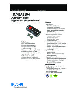
1 LM2734 VIN VIN ENBOOSTSWFBGNDVOUT C3 L1C1 C2 R1 R2 D1 D2 ONOFFP roductFolderSample &BuyTechnicalDocumentsTools &SoftwareSupport &CommunityLM2734 SNVS288J SEPTEMBER2004 REVISEDDECEMBER2014LM2734 Thin SOT 1-A Load Step-DownDC-DCRegulator1 Features3 DescriptionTheLM2734regulatoris a monolithic,high-1 ThinSOT-6 Packagefrequency,PWMstep-downDC-DCconver terin a 6- 20-VInputVoltageRangepin deviceprovidesall the 18-VOutputVoltageRangeactivefunctionsto providelocalDC-DCconversionwithfast transientresponseand accurateregulation 1-A OutputCurrentin the smallestpossiblePCBarea. 550-kHz(LM2734Y)and (LM2734X)SwitchingFrequenciesWitha minimumof externalcomponentsand onlinedesignsupportthroughWEBENCH,the LM2734 300-m NMOSS witchregulatoris easyto use.
2 The abilityto drive1-A loads 30-nAShutdownCurrentwith an internal300-m NMOS switchusingstate-of- ,2% m BiCMOS technologyresultsin the InternalSoft-Startcircuitryallowsfor on-timesas low as 13 ns, thus current -Mode,PWMO perationsupportingexceptionallyhigh-freq uencyconversion WEBENCH OnlineDesignTooloverthe entire3-V to 20-Vinputoperatingrangedownto the minimumoutputvoltageof V. ThermalShutdownSwitchingfrequencyis internallyset to 550kHz LM2734 XQand LM2734 YQare AEC-Q100 Grade(LM2734Y)or MHz(LM2734X),allowingthe use1 Qualifiedand are Manufacturedon anof extremelysmallsurface-mountinductorsand operatingfrequenciesare veryhigh,efficienciesup to 90%are easyto2 included,featuringanultra-lowstandbycurr entof 30 nA.
3 LocalPoint-of-LoadRegulation CorePowerin HDDsThe LM2734regulatorusescurrent-modecontrolan dinternalcompensationto providehigh-performance Set-TopBoxesregulationovera widerangeof operatingconditions. Battery-PoweredDevicesAdditionalfeatures includeinternalsoft-startcircuitry USBP oweredDevicesto reduceinrushcurrent,pulse-by-pulsecurren tlimit,thermalshutdown,and outputovervoltageprotection. DSLM odems NotebookComputersDeviceInformation(1) AutomotivePARTNUMBERPACKAGEBODYSIZE(NOM) LM2734 SOT(6) x (1) For all availablepackages,see the orderableaddendumatthe end of the LoadCurrentVIN= 5 V, VOUT= V1An IMPORTANTNOTICEat the end of this datasheetaddressesavailability,warranty, changes,use in safety-criticalapplications,intellectual propertymattersand SEPTEMBER2004 Applicationand Pin Configurationand Deviceand Mechanical,Packaging,and RevisionHistoryChangesfromRevisionI (April2013)
4 To RevisionJPage AddedESDR atingstable,FeatureDescriptionsection,De viceFunctionalModes,ApplicationandImplem entationsection,PowerSupplyRecommendatio nssection,Layoutsection,DeviceandDocumen tationSupportsection,andMechanical,Packa ging, 2004 2014, SEPTEMBER2004 REVISEDDECEMBER20145 Pin Configurationand FunctionsSee PackageNumberDDC(R-PDSO-G6)6-LeadSOTTop ViewPin drivesthe bootstrapcapacitorisBOOST1 Iconnectedbetweenthe BOOSTand SW Powergroundpin. Placethe bottomresistorof the feedbacknetworkas closeasGND2 GNDpossibleto this pin for ConnectFB to the externalresistordividerto set not allowthis pin to float or be greaterEN4 Ithan VIN+ bypasscapacitorto this the inductor,catchdiode,and 2004 2014,TexasInstrumentsIncorporatedSubmitD ocumentationFeedback3 ProductFolderLinks.
5 LM2734LM2734 SNVS288J SEPTEMBER2004 (unlessotherwisenoted)(1)(2) SW + (15s)260 CTstgStoragetemperature-65150 C(1)StressesbeyondthoselistedunderAbsolu teMaximumRatingsmay causepermanentdamageto the stressratingsonly,whichdo not implyfunctionaloperationof the deviceat theseor any otherconditionsbeyondthoseindicatedunder RecommendedOperatingConditions. Exposureto absolute-maximum-ratedconditionsfor extendedperiodsmay affectdevicereliability.(2)If Military/Aerospacespecifieddevicesare required,pleasecontactthe TexasInstrumentsSalesOffice/Distributors for (HBM),per ANSI/ESDA/JEDECJS001(1) 2000V(1)JEDEC documentJEP155statesthat 500-VHBM allowssafe manufacturingwith a (unlessotherwisenoted)MINNOMMAXUNITVIN32 0 VSW SW 40125 (1)DDCUNIT6 PINSR JC(top)Junction-to-case(top) C/W JC(bot)Junction-to-case(bottom)thermalre sistancen/a(1)For moreinformationabouttraditionaland new thermalmetrics,see theICPackageThermalMetricsapplicationrep ort, 2004 2014, SEPTEMBER2004 5V, VBOOST- VSW= 5V ensuredby design,test, 25 CTJ= -40 C to 125 CPARAMETERTESTCONDITIONSUNITMIN(1)TYP(2) MAX(1)
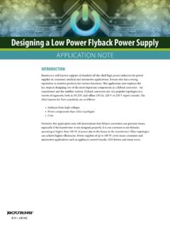
6 VFB/ FeedbackVoltageLineVIN= 3V to / (ON)SwitchON ResistanceVBOOST- VSW= 3V300600m ICLS witchCurrentLimitVBOOST- VSW= 0V30nA(shutdown)LM2734X(50% )IBOOSTB oostPin CurrentmALM2734Y(50% ) CurrentSink/Source10nAISWS witchLeakage40nA(1)Specifiedto AverageOutgoingQualityLevel(AOQL).(2)Typ icalsrepresentthe 2004 2014,TexasInstrumentsIncorporatedSubmitD ocumentationFeedback5 ProductFolderLinks:LM2734LM2734 SNVS288J SEPTEMBER2004 curvestakenat VIN= 5 V, VBOOST- VSW= 5 V and TA= 25 C, OscillatorFrequencyvs Temperature- L1 = HFigure2. OscillatorFrequencyvs Temperature- L1 = 10 HFigure3. CurrentLimitvs TemperatureFigure4. CurrentLimitvs TemperatureVIN= 20 VFigure5.
7 VFBvs TemperatureFigure6. RDSONvs Temperature6 SubmitDocumentationFeedbackCopyright 2004 2014, SEPTEMBER2004 REVISEDDECEMBER2014 TypicalPerformanceCharacteristics(contin ued)All curvestakenat VIN= 5 V, VBOOST- VSW= 5 V and TA= 25 C, IQSwitchingvs TemperatureFigure8. LineRegulation- L1 = HVOUT= V, IOUT= 500 mAFigure9. LineRegulation- L1 = 10 HFigure10. LineRegulation- L1 = HVOUT= V, IOUT= 500 mAVOUT= V, IOUT= 500 mAFigure11. LineRegulation- L1 = 10 HVOUT= V, IOUT= 500 mACopyright 2004 2014,TexasInstrumentsIncorporatedSubmitD ocumentationFeedback7 ProductFolderLinks:LM273400 VINVDTONttInductorCurrentD = TON/TSWVSWTOFFTSWILIPKSWV oltageLM2734 SNVS288J SEPTEMBER2004 a constantfrequencyPWMbuckregulatorIC that deliversa 1-A a presetswitchingfrequencyof either550 kHz (LM2734Y)or MHz(LM2734X).
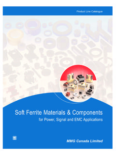
8 Thesehighfrequenciesallowthe LM2734deviceto operatewith smallsurface-mountcapacitorsand inductors,resultinginDC-DCconvertersthat requirea minimumamountof internallycompensated,so it is simpleto use,and requiresfew LM2734deviceusescurrent-modecontrolto regulatethe followingoperatingdescriptionof the LM2734devicewill referto the SimplifiedBlockDiagram() and to thewaveformsin Figure12. The LM2734devicesuppliesa regulatedoutputvoltageby switchingthe internalNMOS controlswitchat constantfrequencyand switchingcyclebeginsat the fallingedgeof theresetpulsegeneratedby the pulsegoeslow, the outputcontrollogicturnson on-time,the SW pin voltage(VSW) swingsup to approximatelyVIN, andthe inductorcurrent(IL) increaseswitha measuredby the current -senseamplifier,whichgeneratesan outputproportionalto the summedwiththe regulator scorrectiverampand comparedto the erroramplifier s output,whichis proportionalto the differencebetweenthefeedbackvoltageand VREF.
9 Whenthe PWMcomparatoroutputgoeshigh,the outputswitchturnsoff switchoff-time,inductorcurrentdischarges throughSchottkydiodeD1,whichforcesthe SW pin to swingbelowgroundby the forwardvoltage(VD) of the regulatorloop adjuststhe duty cycle(D) to maintaina LM2734 Waveformsof SW Pin Voltageand InductorCurrent8 SubmitDocumentationFeedbackCopyright 2004 2014,TexasInstrumentsIncorporatedProduct FolderLinks:LM2734LR1R2D1D2 BOOSTO utputControlLogicCurrentLimitThermalShut downUnderVoltageLockoutCorrective RampResetPulsePWMC omparatorCurrent-Sense AmplifierRSENSE++ :SwitchInternalCompensationSWENFBGNDE rror Amplifier-+ +-CBOOSTVOUTCINVINVINISENSE+-+-+ + SEPTEMBER2004 overvoltagecomparatorcomparesthe FB pin voltageto a voltagethat is 10%higherthanthe FB pin voltagegoes10%abovethe internalreference,the internalNMOS controlswitchis turnedoff, whichallowsthe outputvoltageto (UVLO)preventsthe LM2734fromoperatinguntilthe (typical).
10 The UVLO thresholdhas approximately440 mV of hysteresis,so the part will operateuntil V(typical).Hysteresispreventsthe part fromturningoff duringpowerup if VINis LM2734deviceusescycle-by-cyclecurrentlim itingto protectthe ,a currentlimit comparatordetectsif the A (typical),and turnsoff the switchuntil the next powerdissipationby turningoff the outputswitchwhenthe IC junctiontemperatureexceeds165 C. Afterthermalshutdownoccurs,the outputswitchdoesnot turn on until the junctiontemperaturedropsto approximately150 2004 2014,TexasInstrumentsIncorporatedSubmitD ocumentationFeedback9 ProductFolderLinks:LM2734LM2734 SNVS288J SEPTEMBER2004 / ShutdownModeThe LM2734devicehas a shutdownmodethat is controlledby the enablepin (EN).