Transcription of LT8610 - 42V, 2.5A Synchronous Step-Down …
1 LT861018610faFor more information APPLICATION FEATURESDESCRIPTION42V, Synchronous Step-Down Regulator with A Quiescent CurrentThe LT 8610 is a compact, high efficiency, high speed Synchronous monolithic Step-Down switching regulator that consumes only A of quiescent current. Top and bottom power switches are included with all necessary circuitry to minimize the need for external components. Low ripple Burst Mode operation enables high efficiency down to very low output currents while keeping the output ripple below 10mVP-P. A SYNC pin allows synchronization to an external clock. Internal compensation with peak cur-rent mode topology allows the use of small inductors and results in fast transient response and good loop stability. The EN/UV pin has an accurate 1V threshold and can be used to program VIN undervoltage lockout or to shut down the LT8610 reducing the input supply current to 1 A.
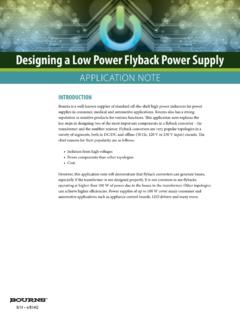
2 A capacitor on the TR/SS pin programs the output voltage ramp rate during start-up. The PG flag signals when VOUT is within 9% of the programmed output voltage as well as fault conditions. The LT8610 is available in a small 16-lead MSOP package with exposed pad for low thermal Step-Down Converter12 VIN to 5 VOUT EfficiencyAPPLICATIONSn Wide Input Voltage Range: to 42Vn Ultralow Quiescent Current Burst Mode Operation: A IQ Regulating 12 VIN to Output Ripple < 10mVP-P n High Efficiency Synchronous Operation: 96% Efficiency at 1A, 5 VOUT from 12 VIN 94% Efficiency at 1A, from 12 VIN n Fast Minimum Switch-On Time: 50nsn Low Dropout Under All Conditions: 200mV at 1An Allows Use Of Small Inductorsn Low EMIn Adjustable and Synchronizable: 200kHz to Current Mode Operationn Accurate 1V Enable Pin Thresholdn Internal Compensationn Output Soft-Start and Trackingn Small Thermally Enhanced 16-Lead MSOP Packagen Automotive and Industrial Suppliesn General Purpose Step-Downn GSM Power SuppliesL, LT , LT C, LT M, Burst Mode, Linear Technology and the Linear logo are registered trademarks of Linear Technology Corporation.
3 All other trademarks are the property of their respective TO 42V1 H1M243kfSW = FLOAD CURRENT (A)0 EFFICIENCY (%)809010028610 = 12 VVIN = 24 VfSW = 700kHzLT861028610faFor more information CONFIGURATIONABSOLUTE MAXIMUM RATINGSVIN, EN/UV, PG ..42 VBIAS ..30 VBST Pin Above SW , TR/SS, RT, INTVCC ..4 VSYNC Voltage ..6 VOperating Junction Temper atur e Range (Note 2) LT8610E .. 40 to 125 C LT8610I .. 40 to 125 C LT8610H .. 40 to 150 CStorage Temper atur e Range .. 65 to 150 C(Note 1)12345678 SYNCTR/SSRTEN/UVVINVINPGNDPGND1615141312 11109 FBPGBIASINTVCCBSTSWSWSWTOP VIEW17 GNDMSE PACKAGE16-LEAD PLASTIC MSOP JA = 40 C/W, JC(PAD) = 10 C/W EXPOSED PAD (PIN 17) IS GND, MUST BE SOLDERED TO PCBELECTRICAL CHARACTERISTICS The l denotes the specifications which apply over the full operating temperature range, otherwise specifications are at TA = 25 INFORMATIONLEAD FREE FINISHTAPE AND REELPART MARKING*PACKAGE DESCRIPTIONTEMPERATURE RANGELT8610 EMSE#PBFLT8610 EMSE#TRPBF861016-Lead Plastic MSOP 40 C to 125 CLT8610 IMSE#PBFLT8610 IMSE#TRPBF861016-Lead Plastic MSOP 40 C to 125 CLT8610 HMSE#PBFLT8610 HMSE#TRPBF861016-Lead Plastic MSOP 40 C to 150 CConsult LT C Marketing for parts specified with wider operating temperature ranges.
4 *The temperature grade is identified by a label on the shipping LT C Marketing for information on non-standard lead based finish more information on lead free part marking, go to: For more information on tape and reel specifications, go to: Input Quiescent CurrentVEN/UV = 0V, VSYNC = 0V 8 A AVEN/UV = 2V, Not Switching, VSYNC = 0V 10 A AVEN/UV = 2V, Not Switching, VSYNC = Current in RegulationVOUT = , VIN = 6V, Output Load = 100 A VOUT = , VIN = 6V, Output Load = 1mAl l24 21050 350 A AFeedback Reference VoltageVIN = 6V, ILOAD = VIN = 6V, ILOAD = VFeedback Voltage Line RegulationVIN = to 42V, ILOAD = Pin Input CurrentVFB = 1V 2020nAINTVCC VoltageILOAD = 0mA, VBIAS = 0V ILOAD = 0mA, VBIAS = VINTVCC Undervoltage Pin Current ConsumptionVBIAS = , ILOAD = 1A, On-TimeILOAD = 1A, SYNC = 0V ILOAD = 1A, SYNC = l30 3050 4570 65ns nsMinimum Off-Time5080110nsLT861038610faFor more information CHARACTERISTICSNote 1: Stresses beyond those listed under Absolute Maximum Ratings may cause permanent damage to the device.
5 Exposure to any Absolute Maximum Rating condition for extended periods may affect device reliability and 2: The LT8610E is guaranteed to meet performance specifications from 0 C to 125 C junction temperature. Specifications over the 40 C to 125 C operating junction temperature range are assured by design, characterization, and correlation with statistical process controls. The LT8610I is guaranteed over the full 40 C to 125 C operating junction temperature range. The LT8610H is guaranteed over the full 40 C to 150 C operating junction temperature range. High junction temperatures degrade operating lifetimes. Operating lifetime is derated at junction The l denotes the specifications which apply over the full operating temperature range, otherwise specifications are at TA = 25 FrequencyRT = 221k, ILOAD = 1A RT = , ILOAD = 1A RT = , ILOAD = 1Al l l180 665 700 735 kHz MHzTop Power NMOS On-ResistanceISW = 1A120m Top Power NMOS Current Power NMOS On-ResistanceVINTVCC = , ISW = 1A65m Bottom Power NMOS Current LimitVINTVCC = Leakage CurrentVIN = 42V, VSW = 0V, 42V AEN/UV Pin ThresholdEN/UV Pin Hysteresis 40mVEN/UV Pin CurrentVEN/UV = 2V 2020nAPG Upper Threshold Offset from VFBVFB Lower Threshold Offset from VFBVFB Risingl 6 12%PG LeakageVPG = 4040nAPG Pull-Down ResistanceVPG = SYNC ThresholdSYNC Falling SYNC VSYNC Pin CurrentVSYNC = 2V 4040nATR/SS Source ATR/SS Pull-Down ResistanceFault Condition.
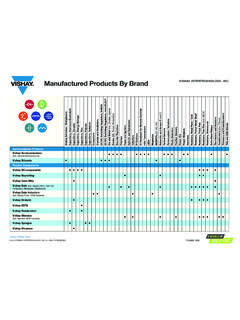
6 TR/SS = temperatures greater than 125 3: This IC includes overtemperature protection that is intended to protect the device during overload conditions. Junction temperature will exceed 150 C when overtemperature protection is active. Continuous operation above the specified maximum operating junction temperature will reduce more information PERFORMANCE CHARACTERISTICSE fficiency at vs FrequencyReference VoltageEN Pin ThresholdsLoad RegulationLine RegulationEfficiency at 5 VOUTE fficiency at at 5 VOUTLOAD CURRENT (A)0 EFFICIENCY (%)809010028610 = 12 VVIN = 24 VfSW = 700kHzLOAD CURRENT (A)0 EFFICIENCY (%)809010028610 = 12 VVIN = 24 VfSW = 700kHzLOAD CURRENT (mA)30 EFFICIENCY (%) 1000100008610 = 12 VVIN = 24 VfSW = 700kHzLOAD CURRENT (mA)30 EFFICIENCY (%) 1000 100008610 = 12 VVIN = 24 VfSW = 700kHzSWITCHING FREQUENCY (MHz) (%)VIN = 12 VVIN = 24 VVOUT = ( C) VOLTAGE (V) 2535155 TEMPERATURE ( C) THRESHOLD (V) RISINGEN FALLINGLOAD CURRENT (A)0 IN VOUT (%) = = 12 VINPUT VOLTAGE (V)0 CHANGE IN VOUT (%)
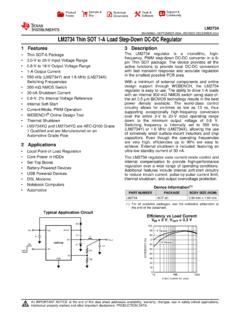
7 G09 = = more information PERFORMANCE CHARACTERISTICSTop FET Current Limit vs Duty CycleTop FET Current LimitBottom FET Current LimitSwitch DropMinimum On-TimeSwitch DropNo Load Supply CurrentNo Load Supply CurrentMinimum Off-TimeINPUT VOLTAGE (V)00 INPUT CURRENT ( A) = REGULATIONTEMPERATURE ( C) 55 250 INPUT CURRENT ( A)1025565958610 G115201535125155 VOUT = = 12 VIN REGULATIONDUTY CYCLE0 CURRENT LIMIT (A) ( C) LIMIT (A) 25535658610 G149512530% DC70% DCTEMPERATURE ( C) LIMIT (A) 25535658610 ( C) 5530 MINIMUM ON-TIME (ns)354550558065565951258610 G1740707560 2535155 ILOAD = 1A, VSYNC = 0 VILOAD = 1A, VSYNC = 3 VILOAD = , VSYNC = 0 VILOAD = , VSYNC = 3 VTEMPERATURE ( C) 50 MINIMUM OFF-TIME (ns)95358610 G188070 25565656010090857595125155 VIN = = ( C) 55 250 SWITCH DROP (mV)100250565958610 G405020015035125155 TOP SWBOT SWSWITCH CURRENT = 1 ASWITCH CURRENT (A)00 SWITCH DROP (mV)5015020025024508610 SWBOT SWLT861068610faFor more information PERFORMANCE CHARACTERISTICSD ropout VoltageSwitching FrequencyBurst FrequencyFrequency FoldbackMinimum Load to Full Frequency (SYNC DC High)Soft-Start TrackingSoft-Start CurrentPG High ThresholdsPG Low ThresholdsLOAD CURRENT (A)0 DROPOUT VOLTAGE (mV)4008610 ( C) 55 SWITCHING FREQUENCY (kHz)730358610 G20700680 25565670660740RT = CURRENT (mA)0 SWITCHING FREQUENCY (kHz)4005006002008610 G21300200050100150100800 VIN = 12 VVOUT = VOLTAGE (V)0 SWITCHING FREQUENCY (kHz) = = 12 VVSYNC = 0 VRT = VOLTAGE (V)0FB VOLTAGE (V) ( C) 50SS PIN CURRENT ( A) = ( C) THRESHOLD OFFSET FROM VREF (%) 2535155FB RISINGFB FALLINGTEMPERATURE ( C)
8 55 THRESHOLD OFFSET FROM VREF (%) G26 2535155FB RISINGFB FALLINGINPUT VOLTAGE (V)LOAD CURRENT (mA)6080100152540458610 G3940200510203035 VOUT = 5 VfSW = 700kHzLT861078610faFor more information PERFORMANCE CHARACTERISTICSRT Programmed Switching FrequencyVIN UVLOBias Pin CurrentBias Pin CurrentSwitching WaveformsSwitching WaveformsSwitching WaveformsTransient ResponseTransient ResponseSWITCHING FREQUENCY (MHz) PIN RESISTOR (k ) ( C) 55 INPUT VOLTAGE (V) VOLTAGE (V)5 BIAS PIN CURRENT (mA) = 5 VVOUT = 5 VILOAD = 1 AfSW = 700kHzSWITCHING FREQUENCY (MHz)00 BIAS PIN CURRENT (mA) = 5 VVOUT = 5 VVIN = 12 VILOAD = 1 AIL1A/DIVVSW5V/DIV500ns/DIV12 VIN TO 5 VOUT AT 1A8610 G31IL200mA/DIVVSW5V/DIV500 s/DIV12 VIN TO 5 VOUT AT 10mAVSYNC = 0V8610 G32IL1A/DIVVSW10V/DIV500ns/DIV36 VIN TO 5 VOUT AT 1A8610 G33 ILOAD1A/DIVVOUT100mV/DIV50 TO TRANSIENT12 VIN, 5 VOUTCOUT = 47 F8610 G34 ILOAD1A/DIVVOUT200mV/DIV50 TO TRANSIENT12 VIN, 5 VOUTCOUT = 47 F8610 G35LT861088610faFor more information FUNCTIONSTYPICAL PERFORMANCE CHARACTERISTICSS tart-Up Dropout PerformanceStart-Up Dropout PerformanceSYNC (Pin 1): External Clock Synchronization Input.
9 Ground this pin for low ripple Burst Mode operation at low output loads. Tie to a clock source for synchronization to an external frequency. Apply a DC voltage of 3V or higher or tie to INTVCC for pulse-skipping mode. When in pulse-skipping mode, the IQ will increase to several hundred A. Do not float this (Pin 2): Output Tracking and Soft-Start Pin. This pin allows user control of output voltage ramp rate during start-up. A TR/SS voltage below forces the LT8610 to regulate the FB pin to equal the TR/SS pin voltage. When TR/SS is above , the tracking function is disabled and the internal reference resumes control of the error amplifier. An internal A pull-up current from INTVCC on this pin allows a capacitor to program output voltage slew rate. This pin is pulled to ground with an internal 230 MOSFET during shutdown and fault conditions; use a series resistor if driving from a low impedance output.
10 This pin may be left floating if the tracking function is not (Pin 3): A resistor is tied between RT and ground to set the switching (Pin 4): The LT8610 is shut down when this pin is low and active when this pin is high. The hysteretic threshold voltage is going up and going down. Tie to VIN if the shutdown feature is not used. An external resistor divider from VIN can be used to program a VIN threshold below which the LT8610 will shut (Pins 5, 6): The VIN pins supply current to the LT8610 internal circuitry and to the internal topside power switch. These pins must be tied together and be locally bypassed. Be sure to place the positive terminal of the input capaci-tor as close as possible to the VIN pins, and the negative capacitor terminal as close as possible to the PGND (Pins 7, 8): Power Switch Ground.