Transcription of LMG3410 600-V 12-A Integrated GaN Power Stage
1 ADVANCE INFORMATIONLDO, VNEGUVLO, OC,TEMPVDD5 VLPMINRDRVC urrentDirect DriveSlew RateEnable Switch600 VGaNDSSVNEGC opyright 2017, texas instruments IncorporatedFAULTP roductFolderOrderNowTechnicalDocumentsTo ols &SoftwareSupport &CommunityAn IMPORTANTNOTICEat the end of this datasheetaddressesavailability,warranty, changes,use in safety-criticalapplications,intellectual propertymattersand pre-productionproducts; APRIL2016 REVISEDNOVEMBER2017 LMG3410600-V 12-A IntegratedGaN PowerStage11 Features1 70-m , 600-VGaNPowerStagefor 12 AOperation IntegratedGateDriver ZeroCommonSourceInductance 20-nsPropagationDelay 1 MHzOperation OnlySingle+12 VUnregulatedSupplyNeeded IntegratedGateDriverBiasSupply Built-inProtectionwith FAULTO utputSignal HighSpeedOver-CurrentProtectionwith<100n sResponseTime Over-temperatureProtection UVLOP rotectionon All SupplyRails Externally-AdjustableDriveStrengthfor SwitchingPerformanceand EMI Control Supports25 to 100 V/ns No Compromisein Gate-driveInductance Auxiliary5V LDOO utput Low Inductance8mmx 8mmQFNP ackageforEasyLayoutand Design2 Applications Totem-PoleCCMand CRMPFC HighfrequencyLLC and PSFB converters SolarInverters MotorDrives Highvoltagebatterycharger3 DescriptionThe LMG3410 Single-ChannelGallium-Nitride(GaN)
2 PowerStagecontainsa 70-m , 600-VGaNpowertransistor,an optimizeddriver,and built-inprotection,in a low inductance8-mmby LMG3410powerstagecoupledwith TI's analoganddigitalpower-conversioncontroll ersenablesdesignersto createsmaller,moreefficientandhigher-per formingdesignscomparedto isolatedhigh-voltageindustrial,telecom, integrateddriverand featuressuchas zeroreverse-recoverycurrent,theLMG3410pr ovidesreliableperformancein hard-switchingapplicationswhereit can dramaticallyreduceswitchinglossesbyas muchas 80 ,the easy-to-useLMG3410integratesbuilt-ininte lligencefor temperature,currentand undervoltagelockout(UVLO)fault ,externally-adjustableslewrateanda low-inductanceQFNpackageminimizeswitchin gloss,voltageringing,and electricalnoisegenerationDeviceInformati on(1)PARTNUMBERPACKAGEBODYSIZE(NOM)LMG34 10 QFN(32) (1) For all availablepackages,see the orderableaddendumatthe end of the INFORMATION2 LMG3410 SNOSD10C APRIL2016 : LMG3410 SubmitDocumentationFeedbackCopyright 2016 2017,TexasInstrumentsIncorporatedTableof Contents1 Pin Configurationand Applicationand 's and Don'ts.
3 1810 Deviceand Mechanical,Packaging,and RevisionHistoryChangesfromRevisionB (March2017)to RevisionCPage (June2016)to RevisionBPage ChangedGan TechnologyPreviewto (April2016)to RevisionAPage Clarifiedpart featureslist on Clarifiedfirst-pagedescriptionto betterdescribefunctionalityof ChangedTheta_JAnumberto Clarifieddefinitionof turn-onand Correctedwordingin Do's and Don'ts Addednoteon MSL3 APRIL2016 REVISEDNOVEMBER2017 ProductFolderLinks: LMG3410 SubmitDocumentationFeedbackCopyright 2016 2017,TexasInstrumentsIncorporated(1)I = Input,O = Output,P = Power5 Pin Configurationand FunctionsRWH(QFN)PACKAGE32 PINS(TopView)Pin FunctionsPINI/O(1) Connectan inductorfromthis pointto sourceDRAIN1-11 PPowertransistordrainFAULT32 OFaultoutput,push-pull,activelowIN31 ICMOS-compatiblenon-invertinggatedrivein putLDO5V25P5-V LDOoutputfor digitalisolator,generatedinternallywith connectingthe pin to sourceSOURCE12-16,18-24 PPowertransistorsource,die-attachpad,the rmalsink,signalgroundreferenceRDRV30 IDrivestrengthselectionpin.
4 Connecta resistorfromthis pin to groundto set the turn-ondrivestrengthto controlslewrate,VDD27P12-Vpowerinput,rel ativeto rail and ,bypassto sourcewith F capacitorNC17 Not connected,connectto sourceor PThermalPad,tie to sourcewith INFORMATION4 LMG3410 SNOSD10C APRIL2016 : LMG3410 SubmitDocumentationFeedbackCopyright 2016 2017,TexasInstrumentsIncorporated(1)Stre ssesbeyondthoselistedunderAbsoluteMaximu mRatingsmay causepermanentdamageto the stressratingsonly,whichdo not implyfunctionaloperationof the deviceat theseor any otherconditionsbeyondthoseindicatedunder RecommendedOperatingConditions. Exposureto absolute-maximum-ratedconditionsfor extendedperiodsmay (unlessotherwisenoted)(1)MINMAXUNITVDSD rain-SourceVoltage600 VVDDS upplyVoltage ,Pulsed 3232 AVININ, LPMPin 55150 CTJO peratingTemperature 40150 C(1)JEDEC documentJEP155statesthat 500-VHBM allowssafe manufacturingwith a standardESDcontrolprocess.(2)JEDEC documentJEP157statesthat 250-VCDM allowssafe manufacturingwith a (ESD)ElectrostaticdischargeHumanbodymode l(HBM),per ANSI/ESDA/JEDECJS-001,all pins(1) 1000 VChargeddevicemodel(CDM),per JEDEC specificationJESD22-C101,all pins(2) (unlessotherwisenoted) Drain-SourceCurrent12AI+5 VLDOE xternalLoadCurrent5mATJO peratingTemperature 40125 C(1)For moreinformationabouttraditionaland new thermalmetrics,see the Semiconductorand IC PackageThermalMetricsapplicationreport,S PRA953.
5 (2)For thermalestimatesof this devicebasedon PCBcopperarea,see the TI PCBT hermalCalculator.(3)The Theta_JAspecificationis basedon a JEDEC2s2pPCBusingthermalvias in still (1) (2) LMG3410 UNITRWH(QFN)32 PINSR JAJunction-to-ambientthermalresistance(3 ) C/WR JC(top)Junction-to-case(top) C/WR JC(bot)Junction-to-case(bottom) C/WADVANCE APRIL2016 REVISEDNOVEMBER2017 ProductFolderLinks: LMG3410 SubmitDocumentationFeedbackCopyright 2016 2017, , V < VDD< 18 V, LPM= 5 V, VNEG= -14 V (unlessotherwisenoted)PARAMETERTESTCONDI TIONSMINTYPMAXUNITGaNPOWERTRANSISTORRDS, ONTotalOn-stateResistanceTJ= 25 C70m TJ= 150 C135 VSDT hird-quadrantmodesource-drainvoltageIN = 0 V, ISD= A5 VIN = 0 V, ISD= 10 600 V, TJ= 25 C15 AVDS= 600 V, TJ= 150 C10 CossGaNoutputcapacitanceIN = 0 V, VDS= 400 V, fSW= 250 kHz71pFCoss,erEffectiveoutputcapacitance ,energyrelatedIN = 0 V, VDS=0-400V95pFCoss,trEffectiveoutputcapa citance,timerelatedID= 5 A, IN = 0 V, VDS= 0-400V145pFQrrReverserecoverychargeVR= 400 V, ISD= 5 A, dISD/dt = 1 A/ns0nCDRIVERSUPPLYIVDD,LPMQ uiescentcurrent,ultra-low-powermodeVLPM= 0 V, VDD= 12 V, TJ= 25 C80125 ATJ= 150 C125 IVDD,QQuiescentcurrent(average)
6 Transistorheld ,opOperatingcurrentVDD= 12 V, fSW= 1 MHz,RDRV=40k , 50%duty cycle43mAV+5V5V LDOoutputvoltageVDD= 12 current ,DCDCDC-DCswitchingfrequencyIOUT= 20 mA1 MHzIDCDC,PKPeakinductorcurrentIOUT= 20 mA, VIN= 12 V, VOUT= -14V250350mA VNEGDC-DCoutputripplevoltage,pk-pkCNEG= 1 F, IOUT= 20 mA200mV DCDCDC-DCconverterefficiencyIOUT= 20 mA, VIN= 12 V, VNEG= -14V75%DRIVERINPUTVIHI nputpin, LPMpin, , LPMpin, low , LPMpin, ,LInputpull-downresistance150k RLPMLPMpin pull-downresistance150k UNDERVOLTAGELOCKOUTVDD, VDD,UVLOUVLOH ysteresis500mVFAULTI tripCurrentFaultTrip Point243650 ATtripTemperatureTrip PointTrip point165 CTtripHysTemperatureTrip Hysteresis20 CADVANCE INFORMATION6 LMG3410 SNOSD10C APRIL2016 : LMG3410 SubmitDocumentationFeedbackCopyright 2016 2017, , V < VDD< 18 V, VNEG= -14 V, VBUS= 400 V (unlessotherwisenoted)PARAMETERTESTCONDITIONSMINTYPMAXUNITGaNFETdv/dtTurn-onDrainSlewRateRDRV= 15 k 100V/nsRDRV= 40 k 50 RDRV= 100 k 25 dv/dtSlewRateVariationturn on, IL= 5 A, RDRV= 40 k 25%dv/dtEdgeRateImmunityDraindv/dt,deviceremainsoffinductor-fed,max di/dt = 10 A/ns150V/nsSTARTUPtSTARTS tartupTime,VINrisingaboveUVLOT imeuntil gaterespondsto IN CNEG= F, CLDO= 1 F2msDRIVERtpd,onPropagationdelay,turn onIN risingto IDS> 10 mA, VDS= 100 VRDRV= 40 k , VNEG= -14 V20nstdelay,onTurnon delaytimeIDS> 1 A to VDS< 320 V, RDRV= 40k 12nstriseRiseTimeVDS= 320 V to VDS= 80 V, ID= 5 ,offPropagationdelay,turn offIN fallingto VDS> 10 V.
7 ID= 5 A36nstfallFall TimeVDS= 80 V to VDS= 320 V, ID= 5 A15nsFAULT tcurrCurrentFaultDelayIDS> ITHto FAULTlow50nstblankCurrentFaultBlankingTi me20nstresetFaultresettimeIN held low350 sADVANCE INFORMATIONS witching Frequency (kHz)Supply Current (mA) = 400 VVDS = 50 VVDS = 0 VDrain-Source Voltage (V)Output Capacitance (pF)050100150200250300350400450500550 6005050701002003004005007001000D001 Source-Drain Current (A)Source-Drain Voltage (V) = 0 VTemperature (qC)Normalized RDS,on-40-20020406080100120140 (k:)Delay (ns)020406080100120140160051015202530354 04550D010ID = 5 APropagation delay (turn on)Turn on delayRise timeDrive Strength Resistor (k:)Drain Slew Rate (V/ns) APRIL2016 REVISEDNOVEMBER2017 ProductFolderLinks: LMG3410 SubmitDocumentationFeedbackCopyright 2016 2017, Turn-onDelaysvs Drive-StrengthResistorFigure2. DrainSlewRatevs Drive-StrengthResistorFigure3. Source-DrainVoltagein 3rd QuadrantOperationFigure4. NormalizedOn Resistancevs TemperatureFigure5. VDDS upplyCurrentvs SwitchingFrequencyFigure6.
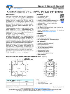
8 OutputCapacitanceADVANCE INFORMATIOND rain Current (A)Switching Energy (PJ)012345678910510152025303540455055606 5707580D008 RDRV = 40 k:Turn-on EnergyTurn-off EnergyRDRV Value (k:)Turn-on Energy (PJ)020406080100120140160404550556065707 580859095100105110115D009ID = 5 A8 LMG3410 SNOSD10C APRIL2016 : LMG3410 SubmitDocumentationFeedbackCopyright 2016 2017,TexasInstrumentsIncorporatedTypical Characteristics(continued)Figure7. Hard-switchedHalf-BridgeTurn-onand Turn-offSwitchingEnergyvs DrainCurrentFigure8. Hard-switchedHalf-BridgeTurn-OnSwitching Energyvs SlewRateResistorADVANCE INFORMATIONC opyright 2017, texas instruments IncorporatedRDRVINFAULT600 VGaNDSTemp, CurrentRDRVINFAULT600 VGaNDSTemp, CurrentVBUS400 VCpcbVDS500 APRIL2016 REVISEDNOVEMBER2017 ProductFolderLinks: LMG3410 SubmitDocumentationFeedbackCopyright 2016 2017,TexasInstrumentsIncorporated7 circuitusedto measuremostswitchingparametersis shownin Figure9. The top LMG3410in this circuitisusedto recirculatethe inductorcurrentand functionsin bottomdeviceis theactivedevice;it is turnedon to increasethe inductorcurrentto the desiredtest bottomdeviceisthenturnedoff and on to createswitchingwaveformsat a draincurrent(at thesource)and the drain-sourcevoltageis specifictimingmeasurementis shownin Figure10.
9 It isrecommendedto use the half-bridgeas quadrantoperationmay overheatthetop CircuitUsedto DetermineSwitchingParametersADVANCE INFORMATION50%50%tpd,offtpd,on20%80%20%8 0%tftrVDSIN1 AIDtdelay,ontdelay,off10 LMG3410 SNOSD10C APRIL2016 : LMG3410 SubmitDocumentationFeedbackCopyright 2016 2017,TexasInstrumentsIncorporatedSwitchi ngParameters(continued)Figure10. Measurementto DeterminePropagationDelaysand timingof the turn-ontransitionis brokeninto threecomponents:propagationdelay,turn-on delayand first componentis the propagationdelayof the driverfromwhenthe inputgoeshigh to whenthe GaNFET startsturningon. The turn-ondelayis the delayfromwhenthe FETstartsturningon (representedby 1 Adraincurrent)to whenthe drainvoltageswingsdownby 20 ,the rise time is the time it takesthedrainvoltageto slewbetween80 percentand 20 percentof the bus drive-strengthresistorvaluehas a largeeffecton turn-ondelayand rise time but doesnot affectthe propagationdelayspecificationis comparableto MOSFET driverswhilethe turn-ondelayand the rise timeare comparableto the per industrystandards,the fall timeof thedrain-sourcevoltageis calledrise timingof the turn-offtransitionis similarlybrokeninto threecomponents:propagationdelay,turn-of fdelayand fall first componentis the propagationdelayof the driverfromwhenthe inputgoeslow to whenthe GaNFET startsturningoff.
10 The turn-offdelayis the delayfromwhenthe FETstartsturningof (representedby the drainrisingabove10 V) to whenthe drainvoltageswingsup by 20 ,the fall timeis thetime it takesthe drainvoltageto slewbetween20 percentand 80 percentof the bus turn-offdelaysof the LMG3410are independentof the drive-strengthresistorbut the turn-offdelayand the fall time are heavilydependenton the load propagationdelayspecificationis comparableto MOSFET driverswhilethe turn-offdelayand the fall timeare comparableto the per industrystandards,the rise timeof thedrain-sourcevoltageis calledfall slewrate,measuredin voltsper nanosecond,is measuredon the turn-onedgeof the slewrate is consideredoverthe rise time,wherethe drainfalls from80 percentto 20 percentof the bus is thusgivenby 60 percentof the bus voltagedividedby the rise isdependenton the RDRV valueand is only slightlyaffectedby APRIL2016 REVISEDNOVEMBER2017 ProductFolderLinks: LMG3410 SubmitDocumentationFeedbackCopyright 2016 2017,TexasInstrumentsIncorporatedSwitchi ngParameters(continued) Turn-offEnergyThe turn-onand turn-offenergy,shownin Figure7, representthe energyabsorbedby the low-sidedeviceduringthe turn-onand turn-offtransientsof the circuitin Figure9, this circuitrepresentsa synchronousbuckconverter,with inputshortedto output,the switchingenergyis dissipatedin the turn-on transitionis lossy,whilethe turn-offtransitionis essentiallylossless;the outputcapacitanceof the devicesischargedby the integratingthe productof the draincurrentwith the drain-sourcevoltageoverthe turn-onand turn-off times, skewof probesfor voltageand currentare very importantfor accuratemeasurementof turn-onand switchingloss of the convertercan be determinedby addingthe turn-onand turn-offenergyin Figure7,adjustingfor the RDRV value(shownin Figure8).