Transcription of Load Transient Response Testing for Voltage ... - analog.com
1 Application Note 104AN104-1an104fOctober 2006 Figure 2. A Practical Regulator Load tester . FET Driver and Q1 Switch RLOAD. Oscilloscope Monitors Current Probe Output and Regulator ResponseLoad Transient Response Testing for Voltage RegulatorsPractical Considerations for Testing and Evaluating ResultsJim Williams, LT, LTC and LTM are registered trademarks of Linear Technology Corporation. All other trademarks are the property of their respective memory, card readers, microprocessors, disc drives, piezoelectric devices and digitally based sys-tems furnish Transient loads that a Voltage regulator must service.
2 Ideally, regulator output is invariant during a load Transient . In practice, some variation is encountered and becomes problematic if allowable operating Voltage toler-ances are exceeded. This mandates Testing the regulator and its associated support components to verify desired performance under Transient loading conditions. Various methods are employable to generate Transient loads, al-lowing observation of regulator Load Transient GeneratorFigure 1 diagrams a conceptual load Transient generator. The regulator under test drives DC and switched resistive loads, which may be variable.
3 The switched current and output Voltage are monitored, permitting comparison of the nominally stable output Voltage versus load current under static and dynamic conditions. The switched current is either on or off; there is no controllable linear 2 is a practical implementation of the load Transient generator. The Voltage regulator under test is augmented by capacitors which provide an energy reservoir, similar to a mechanical fl ywheel, to aid Transient Response . The size, composition and location of these capacitors, particularly COUT, has a pronounced effect on Transient Response and overall regulator Circuit operation is straightfor-ward.
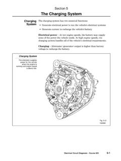
4 The input pulse triggers the LTC1693 FET driver to switch Q1, generating a Transient load current out of the Figure 1. Conceptual Regulator Load tester Includes Switched and DC Loads and Voltage /Current Monitors. Resistor Values Set DC and Switched Load Currents. Switched Current is Either On or Off; There is No Controllable Linear RegionLOADSWITCHCURRENTMONITORAN104 F01 RSWITCHED LOADDC LOADREGULATORUNDER TESTREGULATORINPUT SUPPLY+EREGULATORRSWITCHED LOADEREGULATOR ISWITCHED =VOLTAGEMONITORQ1 IRLZ24TO AC-COUPLEDOSCILLOSCOPECH1CH2 TEKTRONIX P-6042 CURRENTPROBE OR EQUIVALENTMINIMIZEINDUCTANCEPULSEINPUTAN 104 F02 RLOADDC LOADREGULATORUNDER TESTREGULATORINPUT SUPPLY+EREGULATORRSWITCHED LOADEREGULATOR ISWITCHED =CIN10 F+10 COUTO1O2I1I2G2G1VC1 LTC1693-1VC2+Note 1.
5 See Appendix A, Capacitor Parasitic Effects on Load Transient Response and Appendix B, Output Capacitors and Stability for extended Note 104AN104-2an104fregulator. An oscilloscope monitors the instantaneous load Voltage and, via a clip-on wideband probe, current. The circuit s load Transient generating capabilities are evaluated in Figure 3 by substituting an extraordinarily low imped-ance power source for the regulator. The combination of a high capacity power supply, low impedance connec-tions and generous bypassing maintains low impedance across frequency.
6 Figure 4 shows Figure 3 responding to the LTC1693-1 FET driver (Trace A) by cleanly switching 1A in 15ns (Trace B). Such speed is useful for simulating many loads but has restricted versatility. Although fast, the circuit cannot emulate loads between the minimum and maximum point. Q1 s current assumes a value dependant on the control input Voltage and the current sense resis-tor over a very wide bandwidth. Note that once A1 biases to Q1 s conductance threshold, small variations in A1 s output result in large current changes in Q1 s channel.
7 As such, large output excursions are not required from A1; its small signal bandwidth is the fundamental speed limitation. Within this restriction, Q1 s current waveform is identically shaped to A1 s control input Voltage , allow-ing linear control of load current. This versatile capability permits a wide variety of simulated Based CircuitFigure 6, a practical incarnation of a FET based closed loop load Transient generator, includes DC bias and waveform inputs. A1 must drive Q1 s high capacitance gate at high frequency, necessitating high peak A1 output currents and attention to feedback loop compensation.
8 A1, a 60 MHz current feedback amplifi er, has an output current capacity exceeding 1A. Maintaining stability and waveform fi del-ity at high frequency while driving Q1 s gate capacitance necessitates settable gate drive peaking components, a damper network, feedback trimming and loop peaking adjustments. A DC trim, also required, is made fi rst. With no input applied, trim the 1mV adjust for 1mV DC at Q1 s source. The AC trims are made utilizing Figure 7 s arrangement. Similar to Figure 3, this brick wall regulated source provides minimal ripple and sag when step loaded by the load Transient generator.
9 Apply the inputs shown and trim the gate drive, feedback and loop peaking adjust-ments for the cleanest, square cornered Response on the oscilloscope s current probe equipped 3. Substituting Well Bypassed, Low Impedance Power Supply for Regulator Allows Determining Load tester s Response TimeVOLTAGE MONITOR TOAC-COUPLED OSCILLOSCOPE CH1CH2 TEKTRONIX P-6042 CURRENTPROBE OR EQUIVALENTAN104 F03 HEWLETT-PACKARD6012A POWER SUPPLY+PULSELOAD tester (FIGURE 2)++++MINIMIZEINDUCTANCEDC LOAD(OPTIONAL)2200 F*EACH*SANYO OSCON300ns5V3 VCURRENTMONITORAN104 F05 CURRENTSENSE RESISTORREGULATORUNDER TESTREGULATORINPUT SUPPLYCONTROLINPUT+EREGULATORRCURRENT SENSEEINPUTI =VOLTAGEMONITOR +Q1A1 CONTROLAMPLIFIERF igure 5.
10 Conceptual Closed Loop Load tester . A1 Controls Q1 s Source Voltage , Setting Regulator Output Current. Q1 s Drain Current Waveshape is Identical to A1 Input, Allowing Linear Control of Load Current. Voltage and Current Monitors are as in Figure 1 Closed Loop Load Transient GeneratorsFigure 5 s conceptual closed loop load Transient generator linearly controls Q1 s gate Voltage to set instantaneous Transient current at any desired point, allowing simulation of nearly any load profi le. Feedback from Q1 s source to the A1 control amplifi er closes a loop around Q1, stabilizing its Figure 4.