Transcription of Low Cost, General-Purpose High Speed JFET Amplifier Data ...
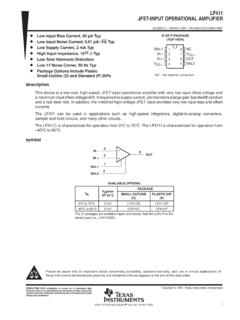
1 Low Cost, General-Purpose High Speed JFET Amplifier Data Sheet AD825. FEATURES CONNECTION DIAGRAMS. High Speed NC 1 8 NC. 41 MHz, 3 dB bandwidth IN 2 AD825 7+VS. TOP VIEW. 125 V/ s slew rate +IN 3. (Not to Scale). 6 OUTPUT. 00876-E-001. VS 4 5 NC. 80 ns settling time Input bias current of 20 pA and noise current of 10 fA/ Hz NC = NO CONNECT. Input voltage noise of 12 nV/ Hz Figure 1. 8-Lead Plastic SOIC (R-8) Package Fully specified power supplies: 5 V to 15 V. Low distortion: 76 dB at 1 MHz NC 1 16 NC. High output drive capability NC 2 15 NC. Drives unlimited capacitance load NC 3 14 NC. 50 mA min output current INPUT 4 AD825 13 +VS. TOP VIEW. No phase reversal when input is at rail +INPUT 5 (Not to Scale) 12 OUTPUT. Available in 8-lead SOIC VS 6 11 NC. NC 7 10 NC. APPLICATIONS. 00876-E-002. NC 8 9 NC. CCDs NC = NO CONNECT. Low distortion filters Figure 2.
2 16-Lead Plastic SOIC (RW-16) Package Mixed gain stages Audio amplifiers Photo detector interfaces ADC input buffers DAC output buffers GENERAL DESCRIPTION. The AD825 is a superbly optimized operational Amplifier for 10V 200ns high Speed , low cost, and dc parameters, making it ideally suited for a broad range of signal conditioning and data acquisition applications. The ac performance, gain, bandwidth, slew rate, and drive capability are all very stable over temperature. The AD825 also maintains stable gain under varying load conditions. The unique input stage has ultralow input bias current and input current noise. Signals that go to either rail on this high performance input do not cause phase reversals at the output. 00876-E-003. These features make the AD825 a good choice as a buffer for 10V. MUX outputs, creating minimal offset and gain errors.
3 The AD825 is fully specified for operation with dual 5 V and Figure 3. Performance with Rail-to-Rail Input Signals 15 V supplies. This power supply flexibility, and the low supply current of mA with excellent ac characteristics under all supply conditions, makes the AD825 well-suited for many demanding applications. Rev. G Document Feedback Information furnished by Analog Devices is believed to be accurate and reliable. However, no responsibility is assumed by Analog Devices for its use, nor for any infringements of patents or other rights of third parties that may result from its use. Specifications subject to change without notice. No One Technology Way, Box 9106, Norwood, MA 02062-9106, license is granted by implication or otherwise under any patent or patent rights of Analog Devices. Tel: 2014 Analog Devices, Inc. All rights reserved.
4 Trademarks and registered trademarks are the property of their respective owners. Technical Support AD825 Data Sheet TABLE OF CONTENTS. Features .. 1 Typical Performance Characteristics ..6. Applications .. 1 Driving Capacitive Loads .. 10. Connection Diagrams .. 1 Theory of Operation .. 10. General Description .. 1 Input Consideration .. 10. Revision History .. 2 Grounding and Bypassing .. 10. 3 Second-Order Low-Pass Filter .. 11. Absolute Maximum Ratings .. 5 Outline Dimensions .. 12. Pin Configurations .. 5 Ordering Guide .. 12. ESD Caution .. 5. REVISION HISTORY. 4/14 Rev. F to Rev. G 2/01 Data Sheet Changed from Rev. C to Rev. D. Updated Outline Dimensions .. 12 Addition of 16- lead soic package (R-16). Changes to Ordering Guide .. 12 Connection Diagram ..4. Addition to Absolute Maximum Ratings ..4. 10/04 Data Sheet Changed from Rev.
5 E to Rev. F. Addition to Ordering Guide (R-16) ..4. Changes to Figure 1 .. 1 Addition of 16- lead soic package (R-16). Changes to Figure 4 .. 5 Outline Dimensions .. 11. Changes to Figure 21 .. 8. 3/04 Data Sheet Changed from Rev. D to Rev. E. Changes to Specifications .. 3. Addition of 16-Lead SOIC Pin Configuration .. 5. Changes to Figure 27 .. 9. Updated Outline Dimensions .. 12. Updated Ordering Guide .. 12. Rev. G | Page 2 of 12. Data Sheet AD825. SPECIFICATIONS. All limits are determined to be at least four standard deviations away from mean value. At TA = 25 C, VS = 15 V, unless otherwise noted. Table 1. AD825A. Parameter Conditions VS Min Typ Max Unit DYNAMIC PERFORMANCE. Unity Gain Bandwidth 15 V 23 26 MHz Bandwidth for dB Flatness Gain = +1 15 V 18 21 MHz 3 dB Bandwidth Gain = +1 15 V 44 46 MHz Slew Rate RLOAD = 1 k , G = +1 15 V 125 140 V/ s Settling Time to 0 V to 10 V Step, AV = 1 15 V 150 180 ns to 0 V to 10 V Step, AV = 1 15 V 180 220 ns Total Harmonic Distortion FC = 1 MHz, G = 1 15 V 77 dB.
6 Differential Gain Error NTSC 15 V %. (RLOAD = 150 ) Gain = +2. Differential Phase Error NTSC 15 V Degrees (RLOAD = 150 ) Gain = +2. INPUT OFFSET VOLTAGE 15 V 1 2 mV. TMIN to TMAX 5 mV. Offset Drift 10 V/ C. INPUT BIAS CURRENT 15 V 15 40 pA. TMIN 5 pA. TMAX 700 pA. INPUT OFFSET CURRENT 15 V 20 30 pA. TMIN 5 pA. TMAX 440 pA. OPEN-LOOP GAIN VOUT = 10 V 15 V. RLOAD = 1 k 70 76 dB. VOUT = V 15 V. RLOAD = 1 k 70 76 dB. VOUT = V 15 V. RLOAD = 150 k (50 mA Output) 68 74 dB. COMMON-MODE REJECTION VCM = 10 15 V 71 80 dB. INPUT VOLTAGE NOISE f = 10 kHz 15 V 12 nV/ Hz INPUT CURRENT NOISE f = 10 kHz 15 V 10 fA/ Hz INPUT COMMON-MODE VOLTAGE RANGE 15 V V. OUTPUT VOLTAGE SWING RLOAD = 1 k 15 V 13 V. RLOAD = 500 15 V V. Output Current 15 V 50 mA. Short-Circuit Current 15 V 100 mA. INPUT RESISTANCE 5 1011 . INPUT CAPACITANCE 6 pF. OUTPUT RESISTANCE Open Loop 8.
7 POWER SUPPLY. Quiescent Current 15 V mA. TMIN to TMAX 15 V mA. Rev. G | Page 3 of 12. AD825 Data Sheet All limits are determined to be at least four standard deviations away from mean value. At TA = 25 C, VS = 5 V unless otherwise noted. Table 2. AD825A. Parameter Conditions VS Min Typ Max Unit DYNAMIC PERFORMANCE. Unity Gain Bandwidth 5 V 18 21 MHz Bandwidth for dB Flatness Gain = +1 5 V 8 10 MHz 3 dB Bandwidth Gain = +1 5 V 34 37 MHz Slew Rate RLOAD = 1 k , G = 1 5 V 115 130 V/ s Settling Time to V to + V 5 V 75 90 ns to V to + V 5 V 90 110 ns Total Harmonic Distortion FC = 1 MHz, G = 1 5 V 76 dB. Differential Gain Error NTSC 5 V %. (RLOAD = 150 ) Gain = +2. Differential Phase Error NTSC 5 V Degrees (RLOAD = 150 ) Gain = +2. INPUT OFFSET VOLTAGE 5 V 1 2 mV. TMIN to TMAX 5 mV. Offset Drift 10 V/ C. INPUT BIAS CURRENT 5 V 10 30 pA. TMIN 5 pA.
8 TMAX 600 pA. INPUT OFFSET CURRENT 5 V 15 25 pA. TMIN 5 pA. Offset Current Drift TMAX 280 pA. OPEN-LOOP GAIN VOUT = 5 V. RLOAD = 500 64 66 dB. RLOAD = 150 64 66 dB. COMMON-MODE REJECTION VCM = 2 V 5 V 69 80 dB. INPUT VOLTAGE NOISE f = 10 kHz 5 V 12 nV/ Hz INPUT CURRENT NOISE f = 10 kHz 5 V 10 fA/ Hz INPUT COMMON-MODE VOLTAGE RANGE 5 V V. OUTPUT VOLTAGE SWING RLOAD = 500 + V. RLOAD = 150 5 V + V. Output Current 5 V 50 mA. Short-Circuit Current 80 mA. INPUT RESISTANCE 5 1011 . INPUT CAPACITANCE 6 pF. OUTPUT RESISTANCE Open Loop 8 . POWER SUPPLY. Quiescent Current 5 V mA. TMIN to TMAX 5 V mA. POWER SUPPLY REJECTION VS = 5 V to 15 V 76 88 dB. Rev. G | Page 4 of 12. Data Sheet AD825. ABSOLUTE MAXIMUM RATINGS PIN CONFIGURATIONS. Table 3. Parameter Rating NC 1 8 NC. Supply Voltage 18 V IN 2 AD825 +VS. 7. TOP VIEW. Internal Power Dissipation1 +IN 3.
9 (Not to Scale). 6 OUTPUT. 00876-E-001. VS 4 5 NC. Small Outline (R) See Figure 6. Input Voltage (Common Mode) VS NC = NO CONNECT. Differential Input Voltage VS Figure 4. 8-Lead SOIC. Output Short-Circuit Duration See Figure 6. Storage Temperature Range (R-8, RW-16) 65 C to +125 C. Operating Temperature Range 40 C to +85 C NC 1 16 NC. 300 C NC 2 15 NC. Lead Temperature Range (Soldering 10 sec) NC 3 14 NC. INPUT 4 AD825 13 +VS. 1. TOP VIEW. Specification is for device in free air: +INPUT 5 (Not to Scale) 12 OUTPUT. 8- lead soic package : JA = 155 C/W VS 6 11 NC. 16- lead soic package : JA = 85 C/W NC 7 10 NC. 00876-E-002. Stresses above those listed under Absolute Maximum Ratings NC 8 9 NC. may cause permanent damage to the device. This is a stress NC = NO CONNECT. rating only; functional operation of the device at these or any Figure 5. 16-Lead SOIC.
10 Other conditions above those indicated in the operational section of this specification is not implied. Exposure to absolute maximum rating conditions for extended periods may affect device reliability. TJ = 150 C. MAXIMUM POWER DISSIPATION (W). 16- lead soic package . 8- lead soic package . 00876-E-004. 0. 50 40 30 20 10 0 10 20 30 40 50 60 70 80 90. AMBIENT TEMPERATURE ( C). Figure 6. Maximum Power Dissipation vs. Temperature ESD CAUTION. Rev. G | Page 5 of 12. AD825. TYPICAL PERFORMANCE CHARACTERISTICS. 20 100. 15. 10 10. OUTPUT IMPEDANCE ( ). OUTPUT SWING (V). 5. RL = 150 RL = 1k . 0 1. 5. 10 15. 00876-E-008. 00876-E-005. 20 0 2 4 6 8 10 12 14 16 18 100 1k 10k 100k 1M 10M. SUPPLY VOLTAGE (V) FREQUENCY (Hz). Figure 7. Output Voltage Swing vs. Supply Voltage Figure 10. Closed-Loop Output Impedance vs. Frequency 15 35 80. 30 BANDWIDTH. 10 UNITY GAIN BANDWIDTH (MHz).