Transcription of LT1167 - Single Resistor Gain Programmable, Precision ...
1 LT116711167fc TYPICAL APPLICATION FEATURES DESCRIPTIONS ingle Resistor Gain Programmable, Precision instrumentation AmplifierThe LT 1167 is a low power, Precision instrumentation amplifier that requires only one external Resistor to set gains of 1 to 10,000. The low voltage noise of Hz (at 1kHz) is not compromised by low power dissipation ( typical for to 15V supplies).The part s high accuracy (10ppm maximum nonlinearity, max gain error (G = 10)) is not degraded even for load resistors as low as 2k. The LT1167 is laser trimmed for very low input offset voltage (40 V max), drift ( V/ C), high CMRR (90dB, G = 1) and PSRR (105dB, G = 1).
2 Low input bias currents of 350pA max are achieved with the use of superbeta processing. The output can handle capacitive loads up to 1000pF in any gain configuration while the inputs are ESD protected up to 13kV (human body). The LT1167 with two external 5k resistors passes the IEC 1000-4-2 level 4 LT1167 , offered in 8-pin PDIP and SO packages, re-quires significantly less PC board area than discrete multi op amp and Resistor LT1167 -1 offers the same performance as the LT1167 , but its input current characteristic at high common mode voltage better supports applications with high input imped-ance (see the Applications Information section).
3 Single Supply Barometer APPLICATIONSn Single Gain Set Resistor : G = 1 to 10,000n Gain Error: G = 10, Maxn Input Offset Voltage Drift: V/ C Maxn Meets IEC 1000-4-2 Level 4 ESD Tests with Two External 5k Resistorsn Gain Nonlinearity: G = 10, 10ppm Maxn Input Offset Voltage: G = 10, 60 V Maxn Input Bias Current: 350pA Maxn PSRR at G = 1: 105dB Minn CMRR at G = 1: 90dB Minn Supply Current: Maxn Wide Supply Range: to 18Vn 1kHz Voltage Noise: Hzn to 10Hz Noise: VP-Pn Available in 8-Pin PDIP and SO Packagesn Bridge Amplifiers Strain Gauge Amplifi ers Thermocouple Amplifi ers Differential to Single -Ended Converters Medical InstrumentationL, LT, LTC, LTM, Linear Technology and the Linear logo are registered trademarks of Linear Technology Corporation.
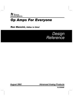
4 All other trademarks are the property of their respective owners. ++ + ACCURACY AT 25 ACCURACY AT 0 C TO 60 CVS = 8V TO 30V5k5k5k5kVS5432 +71/2LT14905628 LUCAS NOVA SENORNPC-1220-015-A-3L7VS61167 TA015TO4-DIGITDVM4R212 LT1167G = 60R1825 VOLTAGE (2V/DIV)NONLINEARITY (100ppm/DIV)1167 TA02G = 1000RL = 1kVOUT = 10 VGain NonlinearityLT116721167fc ABSOLUTE MAXIMUM RATINGSS upply Voltage .. 20 VDifferential Input Voltage (Within theSupply Voltage) .. 40 VInput Voltage (Equal to Supply Voltage) .. 20 VInput Current (Note 3) .. 20mAOutput Short-Circuit Duration .. Indefi niteOperating Temperature Range.
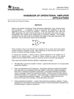
5 40 C to 85 CSpecifi ed Temperature Range LT1167AC/LT1167C/ LT1167AC-1/LT1167C-1 (Note 4) .. 0 C to 70 C LT1167AI/LT1167I/ LT1167AI-1/LT1167I-1 .. 40 C to 85 C Storage Temperature Range .. 65 C to 150 CLead Temperature (Soldering, 10 sec) .. 300 C(Note 1) ORDER INFORMATION PIN CONFIGURATION12348765 TOP VIEWRG IN+IN VSRG+VSOUTPUTREFN8 PACKAGE8-LEAD PDIP+ S8 PACKAGE8-LEAD PLASTIC SOTJMAX = 150 C, JA = 130 C/W (N8)TJMAX = 150 C, JA = 190 C/W (S8)LEAD FREE FINISHTAPE AND REELPART MARKINGPACKAGE DESCRIPTIONSPECIFIED TEMPERATURE RANGELT1167 ACN8#PBFLT1167 ACN8#TRPBFLT1167AC8-Lead PDIP0 C to 70 CLT1167 ACS8#PBFLT1167 ACS8#TRPBF1167A8-Lead Plastic SO0 C to 70 CLT1167 AIN8#PBFLT1167 AIN8#TRPBFLT1167AI8-Lead PDIP 40 C to 85 CLT1167 AIS8#PBFLT1167 AIS8#TRPBF1167AI8-Lead Plastic SO 40 C to 85 CLT1167CN8#PBFLT1167CN8#TRPBFLT1167C8-Le ad PDIP0 C to 70 CLT1167CS8#PBFLT1167CS8#TRPBF11678-Lead Plastic SO0 C to 70 CLT1167IN8#PBFLT1167IN8#TRPBFLT1167I8-Le ad PDIP 40 C to 85 CLT1167IS8#PBFLT1167IS8#TRPBF1167I8-Lead Plastic SO 40 C to
6 85 CLT1167CS8-1#PBFLT1167CS8-1#TRPBF116718- Lead Plastic SO0 C to 70 CLT1167IS8-1#PBFLT1167IS8-1#TRPBF116718- Lead Plastic SO 40 C to 85 CLT1167 ACS8-1#PBFLT1167 ACS8-1#TRPBF116718-Lead Plastic SO0 C to 70 CLT1167 AIS8-1#PBFLT1167 AIS8-1#TRPBF116718-Lead Plastic SO 40 C to 85 CLEAD BASED FINISHTAPE AND REELPART MARKINGPACKAGE DESCRIPTIONSPECIFIED TEMPERATURE RANGELT1167 ACN8LT1167 ACN8#TRLT1167AC8-Lead PDIP0 C to 70 CLT1167 ACS8LT1167 ACS8#TR1167A8-Lead Plastic SO0 C to 70 CLT1167 AIN8LT1167 AIN8#TRLT1167AI8-Lead PDIP 40 C to 85 CLT1167 AIS8LT1167 AIS8#TR1167AI8-Lead Plastic SO 40 C to 85 CLT1167CN8LT1167CN8#TRLT1167C8-Lead PDIP0 C to 70 CLT1167CS8LT1167CS8#TR11678-Lead Plastic SO0 C to 70 CLT1167IN8LT1167IN8#TRLT1167I8-Lead PDIP 40 C to 85 CLT1167IS8LT1167IS8#TR1167I8-Lead Plastic SO 40 C to 85 CConsult LTC Marketing for parts specified with wider operating temperature ranges.
7 *The temperature grade is identified by a label on the shipping container. Consult LTC Marketing for information on non-standard lead based finish more information on lead free part marking, go to: For more information on tape and reel specifications, go to: ELECTRICAL CHARACTERISTICS VS = 15V, VCM = 0V, TA = 25 C, RL = 2k, unless otherwise PARAMETERCONDITIONS (NOTE 7)LT1167AC/LTC1167 AILT1167AC-1/LTC1167AI-1LT1167C/LTC1167 ILT1167C-1/LTC1167I-1 UNITSMINTYPMAXMINTYPMAXGGain RangeG = 1 + ( )110k110kGain ErrorG = 1G = 10 (Note 2)G = 100 (Note 2)G = 1000 (Note 2) Nonlinearity (Note 5)
8 VO = 10V, G = 1VO = 10V, G = 10 and 100VO = 10V, G = = 10V, G = 1, RL = 600VO = 10V, G = 10 and 100, RL = 600VO = 10V, G = 1000, RL = 60056201215656725152080ppmppmppmVOSTT otal Input Referred Offset VoltageVOST = VOSI + VOSO/GVOSII nput Offset VoltageG = 1000, VS = 5V to 15V15402060 VVOSOO utput Offset VoltageG = 1, VS = 5V to 15V4020050300 VIOSI nput Offset Current90320100450pAIBI nput Bias Current5035080500pAenInput Noise Voltage (Note 8) to 10Hz, G = to 10Hz, G = to 10Hz, G = 100 and VP-P VP-P VP-PTotal RTI Noise = eni2 + (eno/G)2 (Note 8)eniInput Noise Voltage Density (Note 8)fO = HzenoOutput Noise Voltage Density (Note 8)fO = 1kHz (Note 3)67906790nV/ HzinInput Noise CurrentfO = to 10Hz1010pAP-PInput Noise Current DenstyfO = 10Hz124124fA/ HzRINI nput ResistanceVIN = 10V20010002001000G CIN(DIFF)Differential Input CapacitancefO = (CM)
9 Common Mode Input CapacitancefO = Voltage RangeG = 1, Other Input Grounded VS = to 5V VS = 5V to 18V VS + VS + +VS +VS VS + VS + +VS +VS Mode Rejection Ratio1k Source Imbalance, VCM = 0V to 10V G = 1 G = 10 G = 100 G = 1000901061201269511512514085100110120951 15125140dBdBdBdBPSRRP ower Supply Rejection RatioVS = to 18V G = 1 G = 10 G = 100 G = 1000 1051251311351201351401501001201261301201 35140150dBdBdBdBISS upply CurrentVS = to Voltage SwingRL = 10k VS = to 5V VS = 5V to 18V VS + VS + +VS +VS VS + VS + +VS +VS ELECTRICAL CHARACTERISTICS VS = 15V, VCM = 0V, TA = 25 C, RL = 2k, unless otherwise l denotes the specifications which apply over the full operating temperature range.
10 Otherwise specifications are at TA = 25 C. VS = 15V, VCM = 0V, 0 C TA 70 C, RL = 2k, unless otherwise PARAMETERCONDITIONS (NOTE 7)LT1167AC/LTC1167 AILT1167AC-1/LTC1167AI-1LT1167C/LTC1167 ILT1167C-1/LTC1167I-1 UNITSMINTYPMAXMINTYPMAXIOUTO utput Current20272027mABWB andwidthG = 1G = 10G = 100G = 1000100080012012100080012012kHzkHzkHzkHz SRSlew RateG = 1, VOUT = sSettling Time to Step G = 1 to 100 G = 10001413014130 s sRREFINR eference Input Resistance2020k IREFINR eference Input CurrentVREF = 0V5050 AVREFR eference Voltage Range VS + +VS VS + +VS Gain to Output1 PARAMETERCONDITIONS (NOTE 7)