Transcription of LT1236 - Precision Reference - Analog Devices
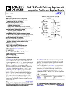
1 1LT1236 Precision ReferenceUAOPPLICATITYPICALDUESCRIPTIOTh e LT 1236 is a Precision Reference that combines ultra-low drift and noise with excellent long-term stability andhigh output accuracy. The Reference output will bothsource and sink up to 10mA and is almost totally immuneto input voltage variations. Two voltages are available: 5 Vand 10V. The 10V version can be used as a shunt regulator(two-terminal zener) with the same Precision characteris-tics as the three-terminal connection. Special care hasbeen taken to minimize thermal regulation effects andtemperature induced LT1236 combines both superior accuracy and tem-perature coefficient specifications without the use of highpower, on-chip heaters. The LT1236 references are basedon a buried zener diode structure which eliminates noiseand stability problems with surface breakdown , a subsurface zener exhibits better temperaturedrift and time stability than even the best Drift: 5ppm/ C MaxnTrimmed to High Accuracy.
2 MaxnIndustrial Temperature Range SO PackagenOperates in Series or Shunt ModenPin Compatible with AD586, AD587nOutput Sinks and Sources in Series ModenVery Low Noise < 1ppm P-P ( to 10Hz)n100% Noise Testedn> 100dB Ripple RejectionnMinimum Input/Output Differential of 1V, LTC and LT are registered trademarks of Linear Technology Distribution of Temperature DriftBasic Positive and Negative ConnectionsLT1236 OUT IN GND LT1236 -10 OUT IN GND VOUT VOUTVINNCR1 = VOUT (V )ILOAD + 15V (V )R1LT1236 TA01 OUTPUT DRIFT (ppm/ C) 30 UNITS (%)4812162422 2 101LT1236 TA02232018141062 DISTRIBUTION OF THREE RUNSUSAOPPLICATInA/D and D/A ConvertersnPrecision RegulatorsnPrecision ScalesnInertial Navigation SystemsnDigital Voltmeters2LT12361 2 3 48 7 6 5 TOP VIEWNC* VIN NC* GNDNC* NC* V0UT TRIM**S8 PACKAGE 8-LEAD PLASTIC SOCONNECTED INTERNALLY.
3 D0 NOT CONNECT EXTERNAL CIRCUITRY TO THESE PINS SEE APPLICATIONS INFORMATION SECTION* ** AUGWAWUWARBSOLUTEXITISI nput Voltage .. 40 VInput/Output Voltage Differential .. 35 VOutput-to-Ground Voltage (Shunt Mode Current Limit) LT1236 -5 .. 10 VLT1236-10 .. 16 VTrim Pin-to-Ground VoltagePositive .. Equal to VOUTN egative .. 20 VOutput Short-Circuit DurationVIN = 35V .. 10 secVIN 20V .. IndefiniteOperating Temperature RangeLT1236AC, BC, CC .. 0 C to 70 CLT1236AI, BI, CI .. 40 C to 85 CStorage Temperature Range .. 65 C to 150 CLead Temperature (Soldering, 10 sec) .. 300 CWUUPACKAGE/ORDER I FOR ATIOC onsult factory for Military grade CCHARA TERISTICSVIN = 10V, IOUT = 0, TA = 25 C, unless otherwise Voltage (Note 1) Voltage Temperature Coefficient (Note 2)TMIN TJ TMAXLT1236A-525ppm/ CLT1236B-5510ppm/ CLT1236C-51015ppm/ CLine Regulation (Note 3) VIN 10V412ppm/Vl20ppm/V10V VIN 40V26ppm/Vl10ppm/VLoad Regulation (Sourcing Current)0 IOUT 10mA1020ppm/mA(Note 3)
4 L35ppm/mALT1236 AIS8-5LT1236 BIS8-5LT1236 CIS8-5LT1236 AIS8-10LT1236 BIS8-10LT1236 CIS8-10 ORDER PARTNUMBERS8 PART MARKINGLT1236 ACS8-5LT1236 BCS8-5LT1236 CCS8-5LT1236 ACS8-10LT1236 BCS8-10LT1236 CCS8-10236AC5236BC5236CC5236AC1236BC1236 CC1236AI5236BI5236CI5236AI1236BI1236CI1 TJMAX = 125 C, JA = 190 C/WTJMAX = 125 C, JA = 130 C/WORDER PARTNUMBERLT1236 ACN8-5LT1236 BCN8-5LT1236 CCN8-5LT1236 ACN8-10LT1236 BCN8-10LT1236 CCN8-10LT1236 AIN8-5LT1236 BIN8-5LT1236 CIN8-5LT1236 AIN8-10LT1236 BIN8-10LT1236 CIN8-101 2 3 48 7 6 5 TOP VIEWNC* VIN NC* GNDNC* NC* V0UT TRIM**N8 PACKAGE 8-LEAD PDIP CONNECTED INTERNALLY. D0 NOT CONNECT EXTERNAL CIRCUITRY TO THESE PINS SEE APPLICATIONS INFORMATION SECTION* ** 3LT1236 ELECTRICAL CCHARA TERISTICSVIN = 10V, IOUT = 0, TA = 25 C, unless otherwise Output Voltage (Note 1) Voltage Temperature Coefficient (Note 2)TMIN TJ TMAXLT1236A-1025ppm/ CLT1236B-10510ppm/ CLT1236C-101015ppm/ CLine Regulation (Note 3) VIN VIN Regulation (Sourcing Current)0 IOUT 10mA1225ppm/mA(Note 3)l40ppm/mALoad Regulation (Shunt Mode) ISHUNT 10mA50100ppm/mA(Notes 3, 4)l150ppm/mASeries Mode Supply Mode Minimum CurrentVIN is Voltage Noise (Note 5) f VP-P10Hz f VRMSLong-Term Stablility of Output Voltage (Note 6) t = 1000 Hrs Non-Cumulative30ppmTemperature Hysteresis of Output (Note 7)
5 T = 25 C5ppmVIN = 15V, IOUT = 0, TA= 25 C, unless otherwise 5: RMS noise is measured with a 2-pole highpass filter at 10Hz and a2-pole lowpass filter at 1kHz. The resulting output is full-wave rectified andthen integrated for a fixed period, making the final reading an average asopposed to RMS. Correction factors are used to convert from average toRMS, and is used to correct for the non-ideal bandbass of the noise is measured with a single highpass filter at and a2-pole lowpass filter at 10Hz. The unit is enclosed in a still-air environmentto eliminate thermocouple effects on the leads. Test time is 10 6: Long-term stability typically has a logarithmic characteristic andtherefore, changes after 1000 hours tend to be much smaller than beforethat time. Total drift in the second thousand hours is normally less thanone third that of the first thousand hours, with a continuing trend towardreduced drift with time.
6 Significant improvement in long-term drift can beThe l denotes specifications which apply over the specified 1: Output voltage is measured immediately after turn-on. Changesdue to chip warm-up are typically less than 2: Temperature coefficient is measured by dividing the change inoutput voltage over the temperature range by the change in slope is also measured at 25 3: Line and load regulation are measured on a pulse basis. Outputchanges due to die temperature change must be taken into 4: Shunt mode regulation is measured with the input open. With theinput connected, shunt mode current can be reduced to 0mA. Loadregulation will remain the Regulation (Sinking Current)0 IOUT 10mA60100ppm/mA(Note 3)l150ppm/mASupply Voltage f VP-P(Note 5)10Hz f VRMSLong-Term Stability of Output Voltage (Note 6) t = 1000 Hrs Non-Cumulative20ppmTemperature Hysteresis of Output (Note 7) T = 25 C10ppm4LT1236 ELECTRICAL CCHARA TERISTICSVIN = 15V, IOUT = 0, TA = 25 C, unless otherwise by preconditioning the IC with a 100-200 hour, 125 C burn term stability will also be affected by differential stresses between theIC and the board material created during board assembly.
7 Temperaturecycling and baking of completed boards is often used to reduce thesestresses in critical 7: Hysteresis in output voltage is created by package stress thatdiffers depending on whether the IC was previously at a higher or lowertemperature. Output voltage is always measured at 25 C, but the IC iscycled to 50 C or 0 C before successive measurements. Hysteresis isroughly proportional to the square of temperature change. Hysteresis isnot normally a problem for operational temperature excursions, but can besignificant in critical narrow temperature range applications where theinstrument might be stored at high or low TERISTICSUWATYPICALPERFORCER ipple RejectionINPUT VOLTAGE (V)085 REJECTION (dB)909510010510203040LT1236 G011101155152535f = 150 HzLT1236-5LT1236-10 FREQUENCY (Hz)1090 REJECTION (dB)11013012010080601001k10kLT1236 G027050 VIN = 15V COUT = 0LT1236-5LT1236-10 Ripple RejectionMinimum Input/OutputDifferential, LT1236 -10 OUTPUT CURRENT (mA)0 INPUT/OUTPUT VOLTAGE (V) = 125 CTJ = 55 CTJ = 25 CStart-Up (Series Mode)TIME ( s) 3 OUTPUT VOLTAGE (V)46781310268LT1236 G0451112904101214LT1236-10LT1236-5 VIN = 0V TO 12 VStart-Up (Shunt Mode), LT1236 -10 Output Voltage Noise SpectrumFREQUENCY (Hz)
8 100 NOISE VOLTAGE (nV/ Hz)200250350400101k1 MLT1236 G06 010030015050LT1236-10LT1236-5 TIME ( s) OUTPUT VOLTAGE (V)9101148LT1236 G0587026101265LT1236-10 IN GNDOUTNC1kVOUT0 VVOUT + 2V5LT1236 CCHARA TERISTICSUWATYPICALPERFORCEO utput Noise to 10Hz, LT1236 -5 TIME (MINUTES)0 35LT1236 G15 1246 OUTPUT VOLTAGE NOISE (5 V/DIV) 5 V (1ppm)FILTERING = 1 ZERO AT 2 POLES AT 10 HzOutput Voltage NoiseBANDWIDTH (Hz)108 RMS NOISE ( V)12161410621001k10kLT1236 G0740 COUT = 0 FILTER = 1 POLE fLOW = Voltage Temperature DriftLT1236-5 OUTPUT CURRENT (mA) 10 OUTPUT CHANGE (mV)135420 2 46LT1236 G09 1 3 5 6 8 4048 2210 VIN = 8 VSOURCINGSINKINGLoad Regulation LT1236 -5 Quiescent Current, LT1236 -5 INPUT VOLTAGE (V)00 INPUT CURRENT (mA) = 55 CTJ = 25 CTJ = 125 CIOUT = 0 Thermal Regulation, LT1236 -5 TIME (ms) OUTPUT CHANGE (mV) G12 2060100 004080120 LOAD REGULATIONTHERMAL REGULATION*ILOAD = 10mA*INDEPENDENT OF TEMPERATURE COEFFICIENTVIN = 25V POWER = 200mWSink Mode* Current Limit, LT1236 -5 OUTPUT VOLTAGE (V)00 CURRENT INTO OUTPUT (mA)10304050481018LT1236 G11202612141660 VIN = 8V*NOTE THAT AN INPUT VOLTAGE IS REQUIRED FOR 5V Transient Response, LT1236 -5, CLOAD = 0 TIME ( s) OUTPUT CHANGE (50mV/DIV)2LT1236 G13102413304 ISOURCE = 2-10mAISOURCE = = 0 ISINK = = 2-10mA50mV50mV ISINK = 100 AP-P ISOURCE = 100 AP-PISOURCE = 0 Load Transient Response, LT1236 -5, CLOAD = 1000pFTIME ( s) OUTPUT CHANGE (20mV/DIV)
9 10LT1236 G1450102051515020 ISOURCE = 2-10mAISOURCE = = 0 ISINK = = 2-10mA20mV20mV ISINK = 100 AP-P ISOURCE = 100 AP-PISOURCE = 0 TEMPERATURE ( C) VOLTAGE (V) 2020801006LT1236 CCHARA TERISTICSUWATYPICALPERFORCELoad Transient Response, LT1236 -10, CLOAD = 0 Load Transient Response, LT1236 -10, CLOAD = 1000pFOutput Noise to 10Hz, LT1236 -10 TIME ( s) OUTPUT VOLTAGE CHANGE 2LT1236 G22102413304 ISOURCE = 2-10mAISOURCE = = = = = 2-10mA10mV50mV ISINK = 100 AP-P ISOURCE = 100 AP-PISOURCE = 0 NOTE VERTICAL SCALE CHANGE BETWEEN SOURCING AND SINKING TIME ( s) OUTPUT VOLTAGE CHANGE 2LT1236 G23102413304 ISOURCE = 2-10mAISOURCE = = = = = 2-10mA5mV20mV ISINK = 100 AP-P ISOURCE = 100 AP-PISOURCE = 0 NOTE VERTICAL SCALE CHANGE BETWEEN SOURCING AND SINKING TIME (MINUTES)0 35LT1236 G24 1246 OUTPUT VOLTAGE NOISE (10 V/DIV) 10 V (1ppm)FILTERING = 1 ZERO AT 2 POLES AT 10 HzOutput Voltage TemperatureDrift, LT1236 -10 OUTPUT CURRENT (mA) 10 OUTPUT CHANGE (mV)135420 2 46LT1236 G17 1 3 5 6 8 4048 2210 VIN = 12 VSOURCINGSINKINGLoad Regulation, LT1236 -10 Input Supply Current, LT1236 -10 INPUT VOLTAGE (V)00 INPUT CURRENT (mA) = 55 CTJ = 25 CTJ = 125 CIOUT = 0 Shunt Mode Current Limit, LT1236 -10 OUTPUT VOLTAGE (V)00 CURRENT INTO OUTPUT (mA)10304050481018LT1236 G20202612141660 INPUT PIN OPENS hunt Characteristics, LT1236 -10 OUTPUT TO GROUND VOLTAGE (V)00 CURRENT INTO OUTPUT (mA) = 55 CTJ = 25 CINPUT PIN OPENTJ = 125 CThermal Regulation, LT1236 -10 TIME (ms) OUTPUT CHANGE (mV)
10 G21 2060100 04080120 LOAD REGULATIONTHERMAL REGULATION*ILOAD = 10mA*INDEPENDENT OF TEMPERATURE COEFFICIENTVIN = 30V POWER = 200mWTEMPERATURE ( C) 40 OUTPUT VOLTAGE (V) INFORMATIONWUUUE ffect of Reference Drift on System AccuracyA large portion of the temperature drift error budget inmany systems is the system Reference voltage. This graphindicates the maximum temperature coefficient allowableif the Reference is to contribute no more than errorto the overall system performance. The example shown isa 12-bit system designed to operate over a temperaturerange from 25 C to 65 C. Assuming the system calibra-tion is performed at 25 C, the temperature span is 40 can be seen from the graph that the temperature coeffi-cient of the Reference must be no worse than 3ppm/ C ifit is to contribute less than error.