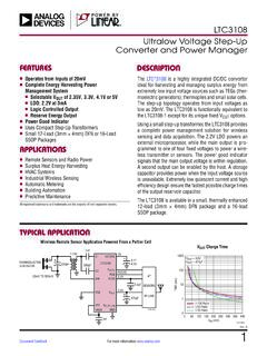
Transcription of LT1962 Series - 300mA, Low Noise, Micropower LDO Regulators
1 LT1962 Series11962fa1962fbFor more information applicaTionDescripTion300mA, Low Noise, Micropower LDO RegulatorsThe LT 1962 Series are Micropower , low noise, low dropout Regulators . The devices are capable of supplying 300mA of output current with a dropout voltage of 270mV. De-signed for use in battery-powered systems, the low 30 A quiescent current makes them an ideal choice. quiescent current is well controlled; it does not rise in dropout as it does with many other key feature of the LT1962 Regulators is low output noise. With the addition of an external F bypass capacitor, output noise drops to 20 VRMS over a 10Hz to 100kHz bandwidth. The LT1962 Regulators are stable with output capacitors as low as F. Small ceramic capacitors can be used without the Series resistance required by other protection circuitry includes reverse battery protec-tion, current limiting, thermal limiting and reverse current protection. The parts come in fixed output voltages of , , , 3V, and 5V, and as an adjustable device with a reference voltage.
2 The LT1962 Regulators are available in the 8-lead MSOP , LT , LT C, LT M, Linear Technology, the Linear logo and Burst Mode are registered trademarks of Linear Technology Corporation. All other trademarks are the property of their respective nLow Noise: 20 VRMS (10Hz to 100kHz) nOutput current : 300mA nLow quiescent current : 30 A nWide Input Voltage Range: to 20V nLow Dropout Voltage: 270mV nVery Low Shutdown current : < 1 A nNo Protection Diodes Needed nFixed Output Voltages: , , , 3V, , 5V nAdjustable Output from to 20V nStable with F Output Capacitor nStable with Aluminum, Tantalum or Ceramic Capacitors nReverse Battery Protection nNo Reverse current nOvercurrent and Overtemperature Protected n8-Lead MSOP Package nCellular Phones nBattery-Powered Systems nNoise-Sensitive Instrumentation Low Noise RegulatorDropout F10 F1962 AT 300mA20 VRMS NOISE1 F+LOAD current (mA)0 DROPOUT VOLTAGE (mV)4003503002502001501005001962 TA0210020030050150250LT1962 Series21962fa1962fbFor more information The l denotes the specifications which apply over the full operating temperature range, otherwise specifications are at TA = 25 C.
3 (Note 3)absoluTe MaxiMuM raTingsIN Pin Voltage .. 20 VOUT Pin Voltage .. 20 VInput to Output Differential Voltage (Note 2) .. 20 VSENSE Pin Voltage .. 20 VADJ Pin Voltage .. 7 VBYP Pin Voltage .. Pin Voltage .. 20 VOutput Short-Circuit Duration ..IndefiniteOperating Junction Temper atur e Range (Note 3) .. 40 C to 125 CStorage Temper atur e Range .. 65 C to 150 CLead Temper atur e (Soldering, 10 sec) ..300 CelecTrical characTerisTicsPARAMETERCONDITIONSMINTYP MAXUNITSM inimum Operating VoltageLT1962 ILOAD = 300mA (Notes 4, 12) Output Voltage (Notes 4, 5) VIN = 2V, ILOAD = 1mA < VIN < 20V, 1mA < ILOAD < 300mA VIN = , ILOAD = 1mA < VIN < 20V, 1mA < ILOAD < 300mA VIN = 3V, ILOAD = 1mA < VIN < 20V, 1mA < ILOAD < 300mA VLT1962-3 VIN = , ILOAD = 1mA 4V < VIN < 20V, 1mA < ILOAD < 300mA VIN = , ILOAD = 1mA < VIN < 20V, 1mA < ILOAD < 300mA VLT1962-5 VIN = , ILOAD = 1mA 6V < VIN < 20V.
4 1mA < ILOAD < 300mA VorDer inForMaTionLEAD FREE FINISHTAPE AND REELPART MARKING*PACKAGE DESCRIPTIONTEMPERATURE RANGELT1962 EMS8#PBFLT1962 EMS8#TRPBFLTML8-Lead Plastic MSOP 40 C to 125 CLT1962 IMS8#PBFLT1962 IMS8#TRPBFLTML8-Lead Plastic MSOP 40 C to 125 # #TRPBFLTSZ8-Lead Plastic MSOP 40 C to 125 # #TRPBFLTTA8-Lead Plastic MSOP 40 C to 125 # #TRPBFLT PT8-Lead Plastic MSOP 40 C to 125 CLT1962 EMS8-3#PBFLT1962 EMS8-3#TRPBFLTPQ8-Lead Plastic MSOP 40 C to 125 # #TRPBFLTPS8-Lead Plastic MSOP 40 C to 125 CLT1962 EMS8-5#PBFLT1962 EMS8-5#TRPBFLTPR8-Lead Plastic MSOP 40 C to 125 CConsult LT C Marketing for parts specified with wider operating temperature ranges. *The temperature grade is identified by a label on the shipping container. Consult LT C Marketing for information on nonstandard lead based finish more information on lead free part marking, go to: For more information on tape and reel specifications, go to: conFiguraTion1234 OUTSENSE/ADJ*BYPGND8765 INNCNCSHDNTOP VIEWMS8 PACKAGE8-LEAD PLASTIC MSOP TJMAX = 150 C, JA = 125 C/W *PIN 2: SENSE FOR LT1962 -5.
5 ADJ FOR LT1962 (Note 1) LT1962 Series31962fa1962fbFor more information The l denotes the specifications which apply over the full operating temperature range, otherwise specifications are at TA = 25 C. (Note 3)elecTrical characTerisTicsPARAMETERCONDITIONSMINTYP MAXUNITSADJ Pin Voltage (Notes 4, 5) LT1962 VIN = 2V, ILOAD = 1mA < VIN < 20V, 1mA < ILOAD < 300mA VLine VIN = 2V to 20V, ILOAD = 1mA VIN = to 20V, ILOAD = 1mA VIN = 3V to 20V, ILOAD = 1mA LT1962 -3 VIN = to 20V, ILOAD = 1mA VIN = to 20V, ILOAD = 1mA LT1962 -5 VIN = to 20V, ILOAD = 1mA LT1962 (Note 4) VIN = 2V to 20V, ILOAD = 1mAl l l l l l l1 1 1 1 1 1 15 5 5 5 5 5 5mV mV mV mV mV mV mVLoad VIN = , ILOAD = 1mA to 300mA VIN = , ILOAD = 1mA to 300mA l38 15mV VIN = , ILOAD = 1mA to 300mA VIN = , ILOAD = 1mA to 300mA l49 18mV VIN = , ILOAD = 1mA to 300mA VIN = , ILOAD = 1mA to 300mA l512 25mV mVLT1962-3 VIN = 4V, ILOAD = 1mA to 300mA VIN = 4V, ILOAD = 1mA to 300mA l715 30mV VIN = , ILOAD = 1mA to 300mA VIN = , ILOAD = 1mA to 300mA l717 33mV mVLT1962-5 VIN = 6V, ILOAD = 1mA to 300mA VIN = 6V, ILOAD = 1mA to 300mA l1225 50mV mVLT1962 (Note 4) VIN = , ILOAD = 1mA to 300mA VIN = , ILOAD = 1mA to 300mA l26 12mV mVDropout Voltage VIN = VOUT(NOMINAL) (Notes 6, 7, 12)ILOAD = 10mA ILOAD = 10mA VILOAD = 50mA ILOAD = 50mA VILOAD = 100mA ILOAD = 100mA VILOAD = 300mA ILOAD = 300mA VGND Pin current VIN = VOUT(NOMINAL) (Notes 6, 8)
6 ILOAD = 0mA ILOAD = 1mA ILOAD = 50mA ILOAD = 100mA ILOAD = 300mAl l l l l30 65 2 875 120 3 12 A A mA mA mAOutput Voltage NoiseCOUT = 10 F, CBYP = F, ILOAD = 300mA, BW = 10Hz to 100kHz20 VRMSADJ Pin Bias current (Notes 4, 9)30100nAShutdown ThresholdVOUT = Off to On VOUT = On to Offl l VSHDN Pin current (Note 10)VSHDN = 0V VSHDN = 5 A AQuiescent current in ShutdownVIN = 6V, VSHDN = ARipple RejectionVIN VOUT = (Avg), VRIPPLE = , fRIPPLE = 120Hz, ILOAD = 300mA5565dBCurrent LimitVIN = 7V, VOUT = 0V VIN = VOUT(NOMINAL) + 1V, VOUT = l 320700mA mAInput Reverse Leakage CurrentVIN = 20V, VOUT = 0Vl1mALT1962 Series41962fa1962fbFor more information Dropout VoltageGuaranteed Dropout VoltageDropout VoltageOUTPUT current (mA)0 DROPOUT VOLTAGE (mV)1502002501502501962 G0110050050100200300350400300TJ = 125 CTJ = 25 COUTPUT current (mA)00 GUARANTEED DROPOUT VOLTAGE (mV)100200300501001502001962 G0225040050050150250350450300= TEST POINTSTJ 125 CTJ 25 CTEMPERATURE ( C) 50 DROPOUT VOTLAGE (mV)350251962 G03200100 2505050040030025015075100125IL = 300mAIL = 100mAIL = 50mAIL = 10mAIL = 1mAPARAMETERCONDITIONSMINTYPMAXUNITSR everse Output current (Note 11) VOUT = , VIN < VOUT = , VIN < VOUT = , VIN < LT1962 -3 VOUT = 3V, VIN < 3V VOUT = , VIN < LT1962 -5 VOUT = 5V, VIN < 5V LT1962 (Note 4) VOUT = , VIN < 10 10 10 10 10 520 20 20 20 20 20 10 A A A A A A A The l denotes the specifications which apply over the full operating temperature range, otherwise specifications are at TA = 25 C.
7 (Note 3)elecTrical characTerisTicsNote 1: Stresses beyond those listed under Absolute Maximum Ratings may cause permanent damage to the device. Exposure to any Absolute Maximum Rating condition for extended periods may affect device reliability and 2: Absolute maximum input to output differential voltage cannot be achieved with all combinations of rated IN pin and OUT pin voltages. With the IN pin at 20V, the OUT pin may not be pulled below 0V. The total measured voltage from in to out can not exceed 3: The LT1962 is tested and specified under pulse load conditions such that TJ TA. The LT1962E is tested at TA = 25 C and performance is guaranteed from 0 C to 125 C. Performance of the LT1962E over the full 40 C to 125 C operating temperature range is assured by design, characterization, and correlation with statistical process controls. The LT1962I is guaranteed over the full 40 C to 125 C operating junction temperature range. Note 4: The LT1962 (adjustable version) is tested and specified for these conditions with the ADJ pin connected to the OUT 5: Operating conditions are limited by maximum junction temperature.
8 The regulated output voltage specification will not apply for all possible combinations of input voltage and output current . When operating at maximum input voltage, the output current range must be limited. When operating at maximum output current , the input voltage range must be 6: To satisfy requirements for minimum input voltage, the LT1962 (adjustable version) is tested and specified for these conditions with an external resistor divider (two 250k resistors) for an output voltage of The external resistor divider will add a 5 A DC load on the 7: Dropout voltage is the minimum input to output voltage differential needed to maintain regulation at a specified output current . In dropout, the output voltage will be equal to: VIN 8: GND pin current is tested with VIN = VOUT(NOMINAL) or VIN = (whichever is greater) and a current source load. This means the device is tested while operating in its dropout region. This is the worst-case GND pin current . The GND pin current will decrease slightly at higher input 9: ADJ pin bias current flows into the ADJ 10: SHDN pin current flows into the SHDN pin.
9 This current is included in the specification for GND pin 11: Reverse output current is tested with the IN pin grounded and the OUT pin forced to the rated output voltage. This current flows into the OUT pin and out the GND 12: For the LT1962 , and dropout voltage will be limited by the minimum input voltage specification under some output voltage/load conditions. See the curve of Minimum Input Voltage in the Typical Performance Characteristics section. For other fixed voltage versions of the LT1962 , the minimum input voltage is limited by the dropout perForMance characTerisTicsLT1962 Series51962fa1962fbFor more information perForMance characTerisTicsQuiescent Output Output VoltageTEMPERATURE ( C) 500 quiescent current ( A)51520255035050751962 G0410404530 2525100125 VIN = 6 VVSHDN = VINRL = , IL = 0 ( )RL = 250k, IL = 5 A ( LT1962 )TEMPERATURE ( C) 50 OUTPUT VOLTAGE (V)1251962 G05050100 = 1mATEMPERATURE ( C) 50 OUTPUT VOLTAGE (V)1251962 G06050100 = Output VoltageLT1962-3 Output Output VoltageTEMPERATURE ( C) 50 OUTPUT VOLTAGE (V) = 1mATEMPERATURE ( C) 50 OUTPUT VOLTAGE (V) = 1mATEMPERATURE ( C) 50 OUTPUT VOLTAGE (V) = 1mALT1962-5 Output VoltageLT1962 ADJ Pin quiescent CurrentTEMPERATURE ( C) 50 OUTPUT VOLTAGE (V) = 1mATEMPERATURE ( C) 50 ADJ PIN VOLTAGE (V) = 1mAINPUT VOLTAGE (V)0 quiescent current ( A)
10 800700600500400300200100081962 G122461071359TJ = 25 CRL = VSHDN = VINVSHDN = 0 VLT1962 Series61962fa1962fbFor more information perForMance quiescent quiescent CurrentLT1962-3 quiescent CurrentINPUT VOLTAGE (V)0 quiescent current ( A)800700600500400300200100081962 G132461071359TJ = 25 CRL = VSHDN = VINVSHDN = 0 VINPUT VOLTAGE (V)0 quiescent current ( A)800700600500400300200100081962 G142461071359TJ = 25 CRL = VSHDN = VINVSHDN = 0 VINPUT VOLTAGE (V)0 quiescent current ( A)800700600500400300200100081962 G152461071359TJ = 25 CRL = VSHDN = VINVSHDN = GND Pin GND Pin GND Pin quiescent CurrentLT1962-5 quiescent CurrentLT1962 quiescent CurrentINPUT VOLTAGE (V)0 quiescent current ( A)800700600500400300200100081962 G162461071359TJ = 25 CRL = VSHDN = VINVSHDN = 0 VINPUT VOLTAGE (V)0 quiescent current ( A)800700600500400300200100081962 G172461071359TJ = 25 CRL = VSHDN = VINVSHDN = 0 VINPUT VOLTAGE (V)0 quiescent current ( A)4035302520151050161962 G1848122014261018TJ = 25 CRL = 250kVSHDN = VINVSHDN = 0 VINPUT VOLTAGE (V)0 GND PIN current ( A)50010001500250750125024681962 G1910103579TJ = 25 CVIN = VSHDN*FOR VOUT = = 30 IL = 50mA*RL = 150 IL = 10mA*RL = = 1mA*INPUT VOLTAGE (V)0 GND PIN current ( A)50010001500250750125024681962 G2010103579TJ = 25 CVIN = VSHDN*FOR VOUT = = 36 IL = 50mA*RL = 180 IL = 10mA*RL = = 1mA*INPUT VOLTAGE (V)0 GND PIN current ( A)50010001500250750125024681962 G2110103579TJ = 25 CVIN = VSHDN*FOR VOUT = = 50 IL = 50mA*RL = 250 IL = 10mA*RL = = 1mA* LT1962 Series71962fa1962fbFor more information perForMance characTerisTicsLT1962-3 GND Pin GND Pin CurrentLT1962-5 GND Pin CurrentINPUT VOLTAGE (V)0 GND PIN current ( A)50010001500250750125024681962 G2210103579TJ = 25 CVIN = VSHDN*FOR VOUT = 3 VRL = 60 IL = 50mA*RL = 300 IL = 10mA*RL = 3kIL = 1mA*INPUT VOLTAGE (V)0 GND PIN current ( A)


