Transcription of LT1964 Low Dropout Negative FEATURES - Analog Devices
1 LT196411964fb typical APPLICATION DESCRIPTION200mA, Low Noise, Low Dropout Negative Micropower Regulator The LT 1964 is a micropower low noise, low Dropout nega-tive regulator. The device is capable of supplying 200mA of output current with a Dropout voltage of 340mV. Low quiescent current (30 A operating and 3 A shutdown) makes the LT1964 an excellent choice for battery-pow-ered applications. Quiescent current is well controlled in FEATURES of the LT1964 include low output noise. With the addition of an external F bypass capacitor, output noise is reduced to 30 VRMS over a 10Hz to 100kHz bandwidth.
2 The LT1964 is capable of operating with small capacitors and is stable with output capacitors as low as 1 F. Small ceramic capacitors can be used without the necessary addition of ESR as is common with other regulators. Internal protection circuitry includes reverse output protection, current limiting, and thermal limiting. The device is available with a fi xed output voltage of 5V and as an adjustable device with a reference volt-age. The LT1964 regulators are available in a low profi le (1mm) ThinSOT and the low profi le ( ) 8-pin (3mm 3mm) DFN , LT, LTC and LTM are registered trademarks of Linear Technology Corporation.
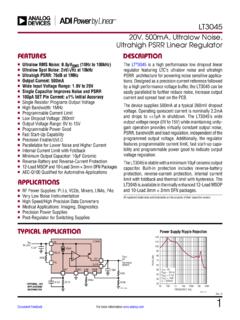
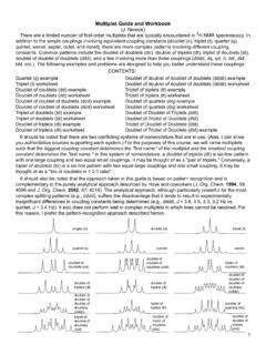
3 ThinSOT is a trademark of Linear Technology Corporation. All other trademarks are the property of their respective owners. FEATURES APPLICATIONSn Low Noise: 30 VRMS (10Hz to 100kHz)n Low Quiescent Current: 30 An Low Dropout Voltage: 340mVn Output Current: 200mAn Fixed Output Voltage: 5Vn Adjustable Output from to 20Vn Positive or Negative Shutdown Logicn 3 A Quiescent Current in Shutdownn Stable with 1 F Output Capacitorn Stable with Aluminum, Tantalum, or Ceramic Capacitorsn Thermal Limitingn Low Profi le (1mm) ThinSOT and ( ) 8-Pin 3mm 3mm DFN Packagesn Battery-Powered Instrumentsn Low Noise Regulator for Noise-Sensitive Instrumentationn Negative Complement to LT1761 Family of Positive LDOs 5V Low Noise Regulator10Hz to 100kHz Output Noise1964 TA01aGNDSHDNBYPINOUTLT1964-51 F10 FVIN 20V 5V AT 200mA30 VRMS NOISEVOUT100 V/DIV1ms/DIV1964 TA01b30 VRMSLT196421964fb ABSOLUTE MAXIMUM RATINGSIN Pin Voltage.
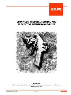
4 20 VOUT Pin Voltage (Note 11) .. 20 VOUT to IN Differential Voltage (Note 11) .. , 20 VADJ Pin Voltage (with Respect to IN Pin) (Note 11) .. , 20 VBYP Pin Voltage (with Respect to IN Pin) .. 20 VSHDN Pin Voltage (with Respect to IN Pin) (Note 11) .. , 35V(Note 1)LT1964LT1964-SDTOP VIEWDD PACKAGE8-LEAD (3mm s 3mm) PLASTIC DFN567894321 OUTOUTADJSHDNININGNDBYPTJMAX = 125 C, JA = 40 C/W, JC = 16 C/W(NOTE 13)EXPOSED PAD (PIN 9) IS IN, MUST BE SOLDERED TO PCB5 OUT4 ADJGND 1 TOP VIEWS5 PACKAGE5-LEAD PLASTIC SOT-23IN 2 SHDN 3 TJMAX = 150 C, JA 125 C/W to 250 C/W(NOTE 13)SEE THE APPLICATIONS INFORMATION SECTIONLT1964-BYPLT1964-55 OUT4 ADJGND 1 TOP VIEWS5 PACKAGE5-LEAD PLASTIC SOT-23IN 2 BYP 3 TJMAX = 150 C, JA 125 C/W to 250 C/W(NOTE 13)
5 SEE THE APPLICATIONS INFORMATION SECTION5 OUT4 SHDNGND 1 TOP VIEWS5 PACKAGE5-LEAD PLASTIC SOT-23IN 2 BYP 3 TJMAX = 150 C, JA 125 C/W to 250 C/W(NOTE 13)SEE THE APPLICATIONS INFORMATION SECTION PIN CONFIGURATIONORDER INFORMATIONLEAD FREE FINISHTAPE AND REELPART MARKING*PACKAGE DESCRIPTIONTEMPERATURE RANGELT1964ES5-SD#PBFLT1964ES5-SD#TRPBFL TVX5-Lead Plastic SOT-23 40 C to 125 CLT1964ES5-BYP#PBFLT1964ES5-BYP#TRPBFLTV Y5-Lead Plastic SOT-23 40 C to 125 CLT1964ES5-5#PBFLT1964ES5-5#TRPBFLTVZ5-L ead Plastic SOT-23 40 C to 125 CLT1964 EDD#PBFLT1964 EDD#TRPBFLDVM8-Lead (3mm 3mm)
6 Plastic DFN 40 C to 125 CLT1964IS5-SD#PBFLT1964IS5-SD#TRPBFLTVX5 -Lead Plastic SOT-23 40 C to 125 CLT1964IS5-BYP#PBFLT1964IS5-BYP#TRPBFLTV Y5-Lead Plastic SOT-23 40 C to 125 CLT1964IS5-5#PBFLT1964IS5-5#TRPBFLTVZ5-L ead Plastic SOT-23 40 C to 125 CLT1964 IDD#PBFLT1964 IDD#TRPBFLDVM8-Lead (3mm 3mm) Plastic DFN 40 C to 125 CSHDN Pin Voltage (with Respect to GND Pin) .. 20V, 15 VOutput Short-Circuit Duration .. Indefi niteOperating Junction Temperature (E, I Grade)Range (Note 10) .. 40 C to 125 CStorage Temperature Range .. 65 C to 150 CLead Temperature (Soldering, 10 sec)SOT-23 Package.
7 300 CLT196431964fb ELECTRICAL CHARACTERISTICS The l denotes the specifi cations which apply over the full operating temperature range, otherwise specifi cations are at TA = 25 Output Voltage(Notes 3, 9) LT1964 -5 VIN = , ILOAD = 1mA 20V < VIN < 6V, 200mA < ILOAD < 1mAl 5 5 Pin Voltage(Notes 2, 3, 9) LT1964 VIN = 2V, ILOAD = 1mA 20V < VIN < , 200mA < ILOAD < 1mAl RegulationLT1964-5 VIN = to 20V, ILOAD = 1mALT1964 (Note 2) VIN = to 20V, ILOAD = 1mAll1515012mVmVLoad RegulationLT1964-5 VIN = 6V, ILOAD = 1mA to 200mA VIN = 6V, ILOAD = 1mA to 200mAl153550mVmVLT1964 VIN = , ILOAD = 1mA to 200mA VIN = , ILOAD = 1mA to 200mAl2715mVmVDropout VoltageVIN = VOUT(NOMINAL)(Notes 4, 5)
8 ILOAD = 1mAILOAD = = 10mAILOAD = = 100mAILOAD = = 200mAILOAD = Pin CurrentVIN = VOUT(NOMINAL)(Notes 4, 6)ILOAD = 0mAILOAD = 1mAILOAD = 10mAILOAD = 100mAILOAD = A A AmAmAORDER INFORMATIONLEAD BASED FINISHTAPE AND REELPART MARKING*PACKAGE DESCRIPTIONTEMPERATURE RANGELT1964ES5-SDLT1964ES5-SD#TRLTVX5-Le ad Plastic SOT-23 40 C to 125 CLT1964ES5-BYPLT1964ES5-BYP#TRLTVY5-Lead Plastic SOT-23 40 C to 125 CLT1964ES5-5LT1964ES5-5#TRLTVZ5-Lead Plastic SOT-23 40 C to 125 CLT1964 EDDLT1964 EDD#TRLDVM8-Lead (3mm 3mm) Plastic DFN 40 C to 125 CLT1964IS5-SDLT1964IS5-SD#TRLTVX5-Lead Plastic SOT-23 40 C to 125 CLT1964IS5-BYPLT1964IS5-BYP#TRLTVY5-Lead Plastic SOT-23 40 C to 125 CLT1964IS5-5LT1964IS5-5#TRLTVZ5-Lead Plastic SOT-23 40 C to 125 CLT1964 IDDLT1964 IDD#TRLDVM8-Lead (3mm 3mm) Plastic DFN 40 C to 125 CConsult LTC Marketing for parts specifi ed with wider operating temperature ranges.
9 *The temperature grade is identifi ed by a label on the shipping more information on lead free part marking, go to: For more information on tape and reel specifi cations, go to: 1: Stresses beyond those listed under Absolute Maximum Ratings may cause permanent damage to the device. Exposure to any Absolute Maximum Rating condition for extended periods may affect device reliability and lifetimeNote 2: The LT1964 (adjustable version) is tested and specifi ed for these conditions with the ADJ pin connected to the OUT 3: Operating conditions are limited by maximum junction temperature.
10 The regulated output voltage specifi cation will not apply for all possible combinations of input voltage and output current. When operating at maximum input voltage, the output current range must be limited. When operating at maximum output current, the input voltage range must be 4: To satisfy requirements for minimum input voltage, the LT1964 (adjustable version) is tested and specifi ed for these conditions with an external resistor divider (two 249k resistors) for an output voltage of The external resistor divider will add a 5 A DC load on the 5: Dropout voltage is the minimum input to output voltage differential needed to maintain regulation at a specifi ed output current.