Transcription of LT3462 (Rev. A) - Analog Devices
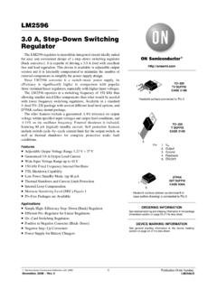
1 LT3462 /LT3462A1 Rev AFor more information FeedbackTYPICAL APPLICATION FEATURESDESCRIPTIONI nverting DC/DC Converters with Integrated Schottky The LT 3462/LT3462A are general purpose fixed fre quency current mode inverting DC/DC converters. Both Devices feature an integrated Schottky and a low VCESAT switch allowing a small converter footprint and lower parts cost. The LT3462 switches at while the LT3462A switches at These high speeds enable the use of tiny, low cost and low height capacitors and LT3462 /LT3462A operate in a dual inductor inverting topology that filters both the input and output currents. Very low output voltage ripple approaching 1mVP P can be achieved when ceramic capacitors are used. fixed fre quency switching ensures a clean output free from low frequency noise typically present with charge pump solu tions.
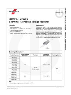
2 The 40V switch allows a VIN to VOUT differential of up to 38V for dual inductor Devices provide a low impedance reference output to supply the feedback resistor network. A ground referenced, high impedance FB input allows high feedback resistor values without compromising output accuracy. APPLICATIONSAll registered trademarks and trademarks are the property of their respective owners. 5V to 5V, 100mA Inverting DC/DC ConverterEfficiency nIntegrated Schottky Rectifier nFixed Frequency Operation nVery Low Noise: 1mVP-P Output Ripple nLow VCESAT Switch: 270mV at 250mA n 5V at 100mA from 5V Input n 12V at 30mA from Input nLow Input Bias Current GND Based FB Input nLow Impedance (40 ) Reference Output nHigh Output Voltage: Up to 38V nWide Input Range: to 16V nUses Tiny Surface Mount Components nLow Shutdown Current.
3 <10 A nLow Profile (1mm) SOT 23 (ThinSOT ) Package n8 Lead DFN (2mm 2mm ) Package, LT3462A Only nCCD Bias nLCD Bias nGaAs FET Bias nGeneral Purpose Negative Voltage SupplyVIN5V22 H22 F22pF1 F1 FVOUT 5V100mAVINSWFBSDREFGNDLT3462A3462 TA01 DLOAD CURRENT (mA)0 EFFICIENCY (%)75706560553462 TA01b20408060100 VIN = = 5 VTA = 25 CLT3462/LT3462A2 Rev AFor more information CONFIGURATIONABSOLUTE MAXIMUM RATINGSI nput Voltage (VIN) ..16 VSW Voltage ..40VD Voltage .. 40 VSDREF, FB Voltage .. Ambient Temperature Range (Note 3) .. 40 C to 85 C(Note 1)TOP VIEWFBGNDGNDSWSDREFDNCVINDC PACKAGE (LT3462A ONLY)8-LEAD (2mm 2mm) PLASTIC DFNTJMAX = 125 C, JA = C/WEXPOSED PAD (PIN 9) IS GND941236578123654 TOP VIEWS6 PACKAGE6-LEAD PLASTIC TSOT-23 TJMAX = 125 C, JA = 192 C/WVINDSDREFSWGNDFB ORDER INFORMATIONLEAD FREE FINISHTAPE AND REELPART MARKINGPACKAGE DESCRIPTIONTEMPERATURE RANGELT3462ES6#PBFLT3462ES6#TRPBFLTBBV6 Lead Plastic TSOT 23 40 C to 85 CLT3462 AES6#PBFLT3462 AES6#TRPBFLTBGB6 Lead Plastic TSOT 23 40 C to 85 CLT3462 AEDC#PBFLT3462 AEDC#TRPBFLHGH8 Lead (2mm 2mm) Plastic DFN 40 C to 85 CConsult ADI Marketing for parts specified with wider operating temperature more information on lead free part marking, go to: For more information on tape and reel specifications, go to.
4 Some packages are available in 500 unit reels through designated sales channels with #TRMPBF #orderinfoMaximum Junction Temperature ..125 CStorage Temperature Range .. 65 C to 150 CLead Temperature (Soldering, 10sec) (TSOT 23 Package Only) ..300 CLT3462/LT3462A3 Rev AFor more information CHARACTERISTICSNote 1: Stresses beyond those listed under Absolute Maximum Ratings may cause permanent damage to the device. Exposure to any Absolute Maximum Rating condition for extended periods may affect device reliability and 2: Current flows out of the Operating Operating Voltage16 VSDREF Voltage10 A > ISDREF 80 A Pin Bias Current (Note 2)1550nASDREF Minus FB Voltage10 A > ISDREF 80 A Amp Offset Voltage 1212mVSDREF Reference Source CurrentSDREF > 120180 ASupply CurrentFB = , Not Switching SDREF = 0V, FB = Open, VIN = 10mA ASDREF Line Frequency ( LT3462 ) Frequency (LT3462A) Duty Cycle ( LT3462 ) 90%Maximum Duty Cycle (LT3462A)
5 77%Switch Current Limit300420mASwitch VCESATISW = 250mA270350mVSwitch Leakage CurrentVSW = ARectifier Leakage CurrentVD = ARectifier Forward DropISCHOTTKY = 250mA8001100mVSDREF Voltage Low Off State Pull Up Current123 ASDREF Turn Off Current 300 200 A The l denotes the specifications which apply over the full operating temperature range, otherwise specifications are at TA = 25 C, VIN = 3V, unless otherwise 3: The LT3462E is guaranteed to meet specifications from 0 C to 70 C. Specifications over the 40 C to 85 C operating temperature range are assured by design, characterization and correlation with statistical process AFor more information PERFORMANCE CHARACTERISTICS(TSOT-23/DFN)SW (Pin 1/Pin 4): Switch Pin.
6 Connect to external induc tor L1 and positive terminal of transfer (Pin 2/Pins 2, 3): Ground. Tie directly to local ground (Pin 3/Pin 1): Feedback Pin. Connect resistive divider tap here. Set R1 according to R1 = R2 ( ). In shutdown, a proprietary shutdown bias current cancel lation circuit allows the internal 3 A source to pull up the SDREF pin, even with residual negative voltage on (Pin 4/Pin 8): Dual Function Shutdown and Reference Output Pin. Pull to GND with exter nal N FET to turn regulator off. Turn off pull down and a 2 A internal source will pull SDREF up to turn on the regulator. At turn on, a 180 A internal source pulls the pin to the regulation voltage. The SDREF pin can supply up to 80 A at to bias the feedback resistor divider.
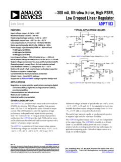
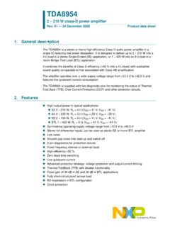
7 An optional soft start circuit capacitor connects from this pin to (Pin 5/Pin 7): Anode Terminal of Integrated Schottky Diode. Connect to negative terminal of transfer cap and external inductor (Pin 6/Pin 5): Input Supply Pin. Must be locally Pad (NA/Pin 9): GND. The exposed pad should be soldered to the PCB ground to achieve the rated ther mal FUNCTIONSO scillator Frequency ( LT3462 )Current LimitSDREF Minus FB Pin VoltageOscillator Frequency (LT3462A)FB Bias CurrentQuiescent Current in Shutdown ModeTEMPERATURE ( C)SDREF MINUS FB (V) G03 DUTY CYCLE (%)10 CURRENT LIMIT (mA)90806040203462 G0230507048036024012003462 G053462 G06 TEMPERATURE ( C) 40 FREQUENCY (MHz) G01 2004080100 TEMPERATURE ( C)FREQUENCY (MHz) 3462 = 25 CSUPPLY VOLTAGE (V)0 QUIESCENT CURRENT (A)1648121086420TA = 25 CFB = N/CTEMPERATURE ( C)FB BIAS CURRENT (nA)801004060200 40 200 5 10 15 20 25 30 35 40 45 50 402060 2004080100 402060 2004080100TA = 25 CLT3462LT3462 ALT3462/LT3462A5 Rev AFor more information DIAGRAMOPERATIONF igure 1.
8 Block DiagramThe LT3462 uses a constant frequency, current mode control scheme to provide excellent line and load regula tion. Operation can be best understood by referring to the Block Diagram in Figure 1. At the start of each oscillator cycle, the SR latch is set, turning on the power switch Q1. A voltage proportional to the switch current is added to a stabilizing ramp and the resulting sum is fed into the positive terminal of the PWM comparator. When this voltage exceeds the voltage at the output of the EAMP, the SR latch is reset, turning off the power switch. The level at the output of the EAMP is simply an amplified version of the difference between the feedback voltage and GND. In this manner, the error amplifier sets the correct peak current level to keep the output in regulation.
9 If the error amplifier s output increases, more current is taken from the output; if it decreases, less current is taken. One func tion not shown in Figure 1 is the current limit. The switch current is constantly monitored and not allowed to exceed the nominal value of 400mA. If the switch current reaches 400mA, the SR latch is reset regardless of the output state of the PWM comparator. This current limit cell protects the power switch as well as various external components connected to the LT3462 . SDREF is a dual function input pin. When driven low it shuts the part down, reducing quiescent supply current to less than 10 A. When not driven low, the SDREF pin has an internal pull up current that turns the regulator on. Once the part is enabled, the SDREF pin sources up to 180 A nominally at a fixed voltage of through external resistor R2 to FB.
10 If there is no fault condition present, FB will regulate to 0V, and VOUT will regulate to ( R1/R2). An optional soft start circuit uses the fixed SDREF pull up current and a capacitor from SDREF to VOUT to set the dV/dt on VOUT. In shutdown, an FB bias current cancellation circuit supplies up to 150 A biasing current to external resistor R1 while VOUT is lower than FB. This function eliminates R2 loading of SDREF during shutdown. As a result, supply current in shutdown may exceed 10 A by the amount of current flowing in R1. + + + +VOUTVOUTDR1 (EXTERNAL)R2 (EXTERNAL)FBRAMPGENERATORSHUTDOWNBIAS *OSCILLATORRSQA1E F01*LT3462A IS (EXTERNAL)CS2 (EXTERNAL)Q2 OFF 3 AON 180 AISRCSHUTDOWNCS1, CS2 OPTIONAL SOFT-START COMPONENTSDOLGLT3462/LT3462A6 Rev AFor more information INFORMATIONI nrush CurrentThe LT3462 has a built in Schottky diode.