Transcription of LTC3350 - High Current Supercapacitor Backup …
1 LTC335013350fcFor more information applicaTion FeaTuresDescripTionHigh Current Supercapacitor Backup Controller and System MonitorThe LT C 3350 is a Backup power controller that can charge and monitor a series stack of one to four supercapacitors. The LTC3350 s synchronous step-down controller drives N-channel MOSFETs for constant Current /constant voltage charging with programmable input Current limit. In addition, the step-down converter can run in reverse as a step-up converter to deliver power from the Supercapacitor stack to the Backup supply rail. Internal balancers eliminate the need for external balance resistors and each capacitor has a shunt regulator for overvoltage protection. The LTC3350 monitors system voltages, currents, stack capacitance and stack ESR which can all be read over the I2C/ SMBus. The dual ideal diode controller uses N-channel MOSFETs for low loss power paths from the input and supercapacitors to the Backup system supply. The LTC3350 is available in a low profile 38-lead 5mm 7mm QFN surface mount package.
2 High Current Supercapacitor Charger and Backup SupplyapplicaTionsn High Efficiency Synchronous Step-Down CC/CV Charging of One to Four Series Supercapacitorsn Step-Up Mode in Backup Provides Greater Utilization of Stored Energy in Supercapacitorsn 14-Bit ADC for Monitoring System Voltages/Currents, Capacitance and ESRn Active Overvoltage Protection Shuntsn Internal Active Balancers No Balance Resistors n VIN: to 35V, VCAP(n): Up to 5V per Capacitor, Charge/ Backup Current : 10+An Programmable Input Current Limit Prioritizes System Load Over Capacitor Charge Currentn Dual Ideal Diode PowerPath Controller n All N-FET Charger Controller and PowerPath Controllern Compact 38-Lead 5mm 7mm QFN Package n High Current 12V Ride-Through UPSn Servers/Mass Storage/High Availability SystemsL, LT, LT C, LT M, Linear Technology and the Linear logo are registered trademarks and PowerPath are trademarks of Linear Technology Corporation. All other trademarks are the property of their respective owners.
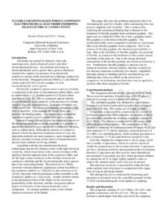
3 Patents OperationVINPFIOUTFBOUTFETTGATESWBGATEIC APVCAPCAP4 CAP3 CAP2 CAP1 CAPRTNCAPFBINFET VOUTSP VOUTSNICHG (STEP-DOWN)IBACKUPVCAP < VOUT(STEP-UP)VCAP > VOUT(DIRECTCONNECT)VOUTLTC335010 FVCAP10F10F10F3350 TA01aI2 CVIN2V/DIVVCAP2V/DIVVOUT2V/DIV400ms/DIVB ACK PAGE APPLICATION CIRCUIT0V3350 TA01aPBACKUP = 25 WVOUTVCAPVINLTC335023350fcFor more information oF conTenTsFeatures ..1 Applications ..1 Typical Application .. 1 Absolute Maximum Ratings ..3 Order Information ..3 Pin Configuration ..3 Electrical Characteristics ..4 Typical Performance Characteristics ..7 Pin Functions ..10 Block Diagram ..13 Timing Diagram .. 14 Introduction ..14 Bidirectional Switching Controller Step-Down Mode ..14 Bidirectional Switching Controller Step-Up Mode 15 Ideal Diodes ..16 Gate Drive Supply (DRVCC) ..17 Undervoltage Lockout (UVLO) ..17RT Oscillator and Switching Frequency ..17 Input Overvoltage Protection ..17 VCAP DAC ..17 Power-Fail (PF) Status Voltage Balancer.
4 17 Capacitor Shunt Regulators ..18I2C/SMBus and SMBALERT ..18 Analog-to-Digital Converter ..18 Capacitance and ESR Measurement ..18 Monitor Status Register ..19 Charge Status Register ..20 Limit Checking and Alarms ..20 Die Temperature Sensor ..20 General Purpose Input ..20 Applications Information ..21 Digital Configuration ..21 Capacitor Configuration ..21 Capacitor Shunt Regulator Programming ..21 Setting Input and Charge Currents ..21 Low Current Charging and High Current Backup ..22 Setting VCAP Voltage ..22 Power-Fail Comparator Input Voltage Threshold .. 22 Setting VOUT Voltage in Backup Mode ..23 Compensation ..24 Minimum VCAP Voltage in Backup Mode ..24 Optimizing Supercapacitor Energy Storage Capacity ..25 Capacitor Selection Procedure ..26 Inductor and CCAP Capacitance ..27 Power MOSFET Selection ..28 Schottky Diode Selection ..28 Top MOSFET Driver Supply (CB, DB) ..29 INTVCC/DRVCC and IC Power Dissipation ..29 Minimum On-Time Diode MOSFET Selection.
5 30 PCB Layout Considerations ..30 Register Map ..32 Register Descriptions ..33 Typical Applications ..39 Package Description ..44 Revision History ..45 Typical Application ..46 Related Parts ..46 LTC335033350fcFor more information conFiguraTionabsoluTe MaxiMuM raTingsVIN, VOUTSP, VOUTSN .. to 40 VVCAP .. to 22 VCAP4-CAP3, CAP3-CAP2, CAP2-CAP1, CAP1-CAPRTN .. to , OUTFB, CAPFB, SMBALERT, CAPGD, PFO, GPI, SDA, SCL .. to .. to .. to 20 VCAP_SLCT0, CAP_SLCT1 .. to 3 VBST to SW .. to to VOUTSN, ICAP to VCAP .. to ..100mAICAP(1,2,3,4), ICAPRTN ..600mAICAPGD, IPFO , ISMBALERT ..10mAOperating Junction Temper atur e Range(Notes 2, 3) .. 40 C to 125 CStorage Temper atur e Range .. 65 C to 150 C(Note 1)13141516 TOP VIEW39 PGNDUHF PACKAGE38-LEAD (5mm 7mm) PLASTIC QFN1718193837363534333224252627282930318 7654321 SCLSDASMBALERTCAPGDVCCAPFBOUTFBSGNDRTGPI ITSTCAPRTNVOUTSPVOUTSNINTVCCDRVCCBGATEBS TTGATESWVCC2P5 ICAPVCAPOUTFETPFOPFICAP_SLCT1 CAP_SLCT0 VININFETVOUTM5 CAP1 CAP2 CAP3 CAP4 CFPCFNVCAPP5232221209101112 TJMAX = 125 C, JA = 34 C/W EXPOSED PAD (PIN 39) IS PGND, MUST BE SOLDERED TO PCBorDer inForMaTionLEAD FREE FINISHTAPE AND REELPART MARKING*PACKAGE DESCRIPTIONTEMPERATURE RANGELTC3350 EUHF#PBFLTC3350 EUHF#TRPBF335038-Lead (5mm 7mm) Plastic QFN 40 C to 125 CLTC3350 IUHF#PBFLTC3350 IUHF#TRPBF335038-Lead (5mm 7mm) Plastic QFN 40 C to 125 CConsult LT C Marketing for parts specified with wider operating temperature ranges.
6 *The temperature grade is identified by a label on the shipping LT C Marketing for information on nonstandard lead based finish more information on lead free part marking, go to: For more information on tape and reel specifications, go to: more information characTerisTics The l denotes the specifications which apply over the specified operating junction temperature range, otherwise specifications are at TA = 25 C (Note 2). VIN = VOUT = 12V, VDRVCC = VINTVCC unless otherwise RegulatorVINI nput Supply Input Quiescent Current (Note 4)4mAVCAPFBHIM aximum Regulated VCAP Feedback Voltage VCAPDAC Full Scale (1111b) VVCAPFBLOM inimum Regulated VCAP Feedback Voltage VCAPDAC Zero Scale (0000b) Input Leakage CurrentVCAPFB = 5050nAVOUTFBR egulated VOUT Feedback Voltage VVOUTFB(TH)OUTFET Turn-Off ThresholdFalling Input Leakage CurrentVOUTFB = 5050nAVOUTBSTVOUT Voltage in Step-Up Mode VIN = Undervoltage LockoutRising Threshold Falling Thresholdl l VVDRVUVLODRVCC Undervoltage LockoutRising Threshold Falling Thresholdl l VVDUVLOVIN VCAP Differential Undervoltage LockoutRising Threshold Falling Thresholdl l145 55185 90225 125mV mVVOVLOVIN Overvoltage LockoutRising Threshold Falling Thresholdl VVVCAPP5 Charge Pump Output VoltageRelative to VCAP, 0V VCAP 20V 5 VInput Current Sense AmplifierVSNSIR egulated Input Current Sense Voltage (VOUTSP VOUTSN) mVCharge Current Sense AmplifierVSNSCR egulated Charge Current Sense Voltage (ICAP VCAP)VCAP = 10V mVVCMCC ommon Mode Range (ICAP, VCAP)
7 020 VVPEAKPeak Inductor Current Sense Voltagel515865mVVREVR everse Inductor Current Sense VoltageStep-Down Pin CurrentStep-Down Mode, VSNSC = 32mV Step-Up Mode, VSNSC = 32mV30 135 A AError AmplifiergMVVCAP Voltage Loop Transconductance1mmhogMCCharge Current Loop Transconductance64 mhogMIInput Current Loop Transconductance64 mhogMOVOUT Voltage Loop Transconductance400 mhoOscillatorfSWSwitching FrequencyRT = 107k l495 490500 500505 510kHz kHzMaximum Programmable Frequency RT = Programmable FrequencyRT = 267k200kHzLTC335053350fcFor more information characTerisTics The l denotes the specifications which apply over the specified operating junction temperature range, otherwise specifications are at TA = 25 C (Note 2). VIN = VOUT = 12V, VDRVCC = VINTVCC unless otherwise Duty CycleStep-Down Mode Step-Up Mode97 8798 %Gate DriversRUP-TGTGATE Pull-Up On-Resistance2 RDOWN-TGTGATE Pull-Down RUP-BGBGATE Pull-Up On-Resistance2 RDOWN-BGBGATE Pull-Down tr-TGTGATE 10% to 90% Rise TimeCLOAD = 10% to 90% Fall TimeCLOAD = 10% to 90% Rise TimeCLOAD = 10% to 90% Fall TimeCLOAD = Time50nstON(MIN) 85nsINTVCC Linear RegulatorVINTVCCI nternal VCC Voltage VIN 35V5V VINTVCCLoad Regulation IINTVCC = 50mA DiodesVFTOF orward Turn-On Voltage65 mVVFRF orward Regulation30mVVRTOR everse Turn Off 30mVtIF(ON)INFET Rise TimeINFET VIN > 3V, CINFET = 560 stIF(OFF)INFET Fall TimeINFET VIN < 1V, CINFET = stOF(ON)OUTFET Rise TimeOUTFET VCAP > 3V, COUTFET = stOF(OFF)OUTFET Fall TimeOUTFET VCAP < 1V, COUTFET = sPower-Fail ComparatorVPFI(TH)PFI Input Threshold (Falling Edge) (HYS)
8 PFI Hysteresis30mVIPFIPFI Input Leakage CurrentVPFI = 5050nAVPFOPFO Output Low VoltageISINK = 5mA200mVIPFOPFO High-Z Leakage CurrentVPFO = 5Vl1 APFI Falling to PFO Low Delay85nsPFI Rising to PFO High sCAPGDVCAPFB(TH)CAPGD Rising Threshold as % of Regulated VCAP Feedback Voltage Vcapfb_dac = Full Scale (1111b)l909294%VCAPFB(HYS)CAPGD Hysteresis at CAPFB as a % of Regulated VCAP Feedback VoltageVcapfb_dac = Full Scale (1111b) Output Low VoltageISINK = 5mA200mVICAPGDCAPGD High-Z Leakage CurrentVCAPGD = 5Vl1 ALTC335063350fcFor more information characTerisTics The l denotes the specifications which apply over the specified operating junction temperature range, otherwise specifications are at TA = 25 C (Note 2). VIN = VOUT = 12V, VDRVCC = VINTVCC unless otherwise ConverterVRESM easurement Resolution16 BitsVGPIG eneral Purpose Input Voltage RangeUnbuffered Buffered0 05 VIGPIG eneral Purpose Input Pin Leakage CurrentBuffered Input 1 ARGPIGPI Pin ResistanceBuffer Measurement System ErrorVERRM easurement Error (Note 5)
9 VIN = 0V VIN = 30V100 %VOUTSP = 5V VOUTSP = 30V100 %VCAP = 0V VCAP = 10V100 %VGPI = 0V, Unbuffered VGPI = , Unbuffered2 1mV %VCAP1 = 0V VCAP1 = 2V2 1mV %VCAP2 = 0V VCAP2 = 2V2 1mV %VCAP3 = 0V VCAP3 = 2V2 1mV %VCAP4 = 0V VCAP4 = 2V2 1mV %VSNSI = 0mV VSNSI = 32mV200 2 V %VSNSC = 0mV VSNSC = 32mV200 2 V %CAP1 to CAP4 RSHNTS hunt DVCAPMAXM aximum Capacitor Voltage with Shunts Enabled 2 or More Capacitors in PinsVITSTITST VoltageRTST = 121 SDA, SCL, SMBALERTIIL,SDA,SCLI nput Leakage Low 11 AIIH,SDA,SCLI nput Leakage High 11 AVIHI nput High Low Clock Frequency400kHztLOWLow Period of SCL stHIGHHigh Period of SCL stBUFBus Free Time Between Start and Stop stHD,STAHold Time, After (Repeated) Start stSU,STAS etup Time After a Repeated Start sLTC335073350fcFor more information characTerisTics The l denotes the specifications which apply over the specified operating junction temperature range, otherwise specifications are at TA = 25 C (Note 2). VIN = VOUT = 12V, VDRVCC = VINTVCC unless otherwise ,STOStop Condition Set-Up stHD,DATOO utput Data Hold Time0900nstHD,DATII nput Data Hold Time0nstSU,DATData Set-Up Time100nstSPInput Spike Suppression Pulse Width50nsVSMBALERTSMBALERT Output Low VoltageISINK = 1mA200mVISMBALERTSMBALERT High-Z Leakage CurrentVSMBALERT = 5Vl1 ANote 1: Stresses beyond those listed under Absolute Maximum Ratings may cause permanent damage to the device.
10 Exposure to any Absolute Maximum Rating condition for extended periods may affect device reliability and lifetime. Note 2: The LTC3350 is tested under pulsed load conditions such that TJ TA. The LTC3350E is guaranteed to meet specifications from 0 C to 125 C junction temperature. Specifications over the 40 C to 125 C operating junction temperature range are assured by design, characterization and correlation with statistical process controls. The LTC3350I is guaranteed over the 40 C to 125 C operating junction temperature range. Note that the maximum ambient temperature consistent with these specifications is determined by specific operating conditions in conjunction with board layout, the rated package thermal impedance and other environmental factors. The junction temperature (TJ, in C) is calculated from the ambient temperature (TA, in C) and power dissipation (PD, in Watts) according to the formula: TJ = TA + (PD JA)where JA = 34 C/W for the UHF 3: The LTC3350 includes overtemperature protection that is intended to protect the device during momentary overload conditions.