Transcription of LTC3787 - PolyPhase Synchronous Boost Controller
1 LTC3787 . PolyPhase Synchronous Boost Controller FEATURES DESCRIPTION. n 2-Phase Operation Reduces Required Input and The LTC 3787 is a high performance PolyPhase single Output Capacitance and Power Supply Induced Noise output Synchronous Boost converter Controller that drives n Synchronous Operation for Highest Efficiency and two N-channel power MOSFET stages out-of-phase. Reduced Heat Dissipation Multiphase operation reduces input and output capacitor n Wide VIN Range: to 38V (40V Abs Max) and requirements and allows the use of smaller inductors than Operates Down to After Start-Up the single-phase equivalent. Synchronous rectification in- n Output Voltage Up to 60V creases efficiency, reduces power losses and eases thermal n 1% Reference Voltage requirements, enabling high power Boost applications.
2 N RSENSE or Inductor DCR Current Sensing n A to 38V input supply range encompasses a wide 100% Duty Cycle Capability for Synchronous MOSFET. n range of system architectures and battery chemistries. Low Quiescent Current: 135 A. n When biased from the output of the Boost converter or Phase-Lockable Frequency (75kHz to 850kHz). n another auxiliary supply, the LTC3787 can operate from Programmable Fixed Frequency (50kHz to 900kHz). n an input supply as low as after start-up. The operat- Power Good Output Voltage Monitor n ing frequency can be set for a 50kHz to 900kHz range or Low Shutdown Current, IQ < 8 A. n synchronized to an external clock using the internal PLL. Internal LDO Powers Gate Drive from VBIAS or EXTVCC. n PolyPhase operation allows the LTC3787 to be configured Thermally Enhanced Low Profile 28-Pin 4mm 5mm for 2-, 3-, 4-, 6- and 12-phase operation.
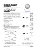
3 QFN Package and Narrow SSOP Package The SS pin ramps the output voltage during start-up. The APPLICATIONS PLLIN/MODE pin selects Burst Mode operation, pulse- skipping mode or forced continuous mode at light loads. n Industrial L, LT, LTC, LTM, Linear Technology, the Linear logo, Burst Mode, OPTI-LOOP and PolyPhase n Automotive are registered trademarks and No RSENSE and ThinSOT are trademarks of Linear Technology Corporation. All other trademarks are the property of their respective owners. Protected by n Medical U. S. Patents, including 5408150, 5481178, 5705919, 5929620, 6144194, 6177787, 6580258. n Military TYPICAL APPLICATION Efficiency and Power Loss 12V to 24V/10A 2-Phase Synchronous Boost Converter vs Output Current VIN TO 24V START-UP VOLTAGE VIN 100 10000.
4 OPERATES THROUGH TRANSIENTS DOWN TO 90. 80 1000. 4m F F 4m 47 F. POWER LOSS (mW). 70. EFFICIENCY (%). TG1 VBIAS INTVCC TG2 60 100. H BOOST1 BOOST2 H 50. F F. SW1 SW2 VOUT 40 10. 24V AT 10A. BG1 LTC3787 30. BG2. SENSE1+ VIN = 12V. 20 1. VOUT = 24V. 232k SENSE1 SENSE2+. VFB 10 Burst Mode OPERATION. FREQ SENSE2 FIGURE 10 CIRCUIT. 0 PLLIN/MODE PGND. 1 10. ITH SS SGND OUTPUT CURRENT (A). 15nF 220 F 3787 TA01b 100pF BURST EFFICIENCY. BURST LOSS. F. 3787 TA01a 3787fc 1. LTC3787 . ABSOLUTE MAXIMUM RATINGS (Notes 1, 3). VBIAS .. to 40V EXTVCC .. to 6V. BOOST1 and BOOST2 .. to 76V SENSE1+, SENSE1 , SENSE2+, SENSE2 .. to 40V. SW1 and to 70V (SENSE1+ - SENSE1 ), (SENSE2+ - SENSE2 ) .. to RUN .. to 8V ILIM, SS, ITH, FREQ, PHASMD, VFB.
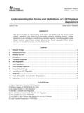
5 To INTVCC. Maximum Current Sourced into Pin Operating Junction Temperature From Source >8V ..100 A Range (Note 2).. 55 C to 150 C. PGOOD, PLLIN/MODE .. to 6V Storage Temperature Range .. 65 C to 150 C. INTVCC, (BOOST1 - SW1), (BOOST2 - SW2) .. to 6V. PIN CONFIGURATION. TOP VIEW TOP VIEW. SENSE1 . SENSE1+. PGOOD. ILIM 1 28 PGOOD. SW1. ILIM. TG1. SENSE1+ 2 27 SW1. SENSE1 3 26 TG1 28 27 26 25 24 23. FREQ 4 25 BOOST1 FREQ 1 22 BOOST1. PHASMD 5 24 BG1 PHASMD 2 21 BG1. CLKOUT 3 20 VBIAS. CLKOUT 6 23 VBIAS. PLLIN/MODE 7 22 PGND PLLIN/MODE 4 29 19 PGND. GND 18 EXTVCC. SGND 5. SGND 8 21 EXTVCC. RUN 6 17 INTVCC. RUN 9 20 INTVCC. SS 7 16 BG2. SS 10 19 BG2. SENSE2 8 15 BOOST2. SENSE2 11 18 BOOST2. 9 10 11 12 13 14. SENSE2+ 12 17 TG2.
6 SENSE2+. VFB. ITH. NC. SW2. TG2. VFB 13 16 SW2. ITH 14 15 NC. UFD PACKAGE. GN PACKAGE 28-LEAD (4mm s 5mm) PLASTIC QFN. 28-LEAD PLASTIC SSOP TJMAX = 125 C, JA = 43 C/W. TJMAX = 125 C, JA = 90 C/W EXPOSED PAD (PIN 29) IS GND, MUST BE CONNECTED TO GND. ORDER INFORMATION. LEAD FREE FINISH TAPE AND REEL PART MARKING* PACKAGE DESCRIPTION TEMPERATURE RANGE. LTC3787 EUFD#PBF LTC3787 EUFD#TRPBF 3787 28-Lead (4mm 5mm) Plastic QFN 40 C to 125 C. LTC3787 IUFD#PBF LTC3787 IUFD#TRPBF 3787 28-Lead (4mm 5mm) Plastic QFN 40 C to 125 C. LTC3787 HUFD#PBF LTC3787 HUFD#TRPBF 3787 28-Lead (4mm 5mm) Plastic QFN 40 C to 150 C. LTC3787 MPUFD#PBF LTC3787 MPUFD#TRPBF 3787 28-Lead (4mm 5mm) Plastic QFN 55 C to 150 C. LTC3787 EGN#PBF LTC3787 EGN#TRPBF LTC3787GN 28-Lead Plastic SSOP 40 C to 125 C.
7 LTC3787 IGN#PBF LTC3787 IGN#TRPBF LTC3787GN 28-Lead Plastic SSOP 40 C to 125 C. LTC3787 HGN#PBF LTC3787 HGN#TRPBF LTC3787GN 28-Lead Plastic SSOP 40 C to 150 C. LTC3787 MPGN#PBF LTC3787 MPGN#TRPBF LTC3787GN 28-Lead Plastic SSOP 55 C to 150 C. Consult LTC Marketing for parts specified with wider operating temperature ranges. *The temperature grade is identified by a label on the shipping container. For more information on lead free part marking, go to: For more information on tape and reel specifications, go to: 3787fc 2. LTC3787 . ELECTRICAL CHARACTERISTICS The l denotes the specifications which apply over the specified operating junction temperature range, otherwise specifications are at TA = 25 C, VBIAS = 12V, unless otherwise noted (Note 2).
8 SYMBOL PARAMETER CONDITIONS MIN TYP MAX UNITS. Main Control Loop VBIAS Chip Bias Voltage Operating Range 38 V. VFB Regulated Feedback Voltage ITH = (Note 4) l V. IFB Feedback Current (Note 4) 5 50 nA. VREFLNREG Reference Line Voltage Regulation VBIAS = 6V to 38V %/V. VLOADREG Output Voltage Load Regulation Measured in Servo Loop; l %. (Note 4) ITH Voltage = to Measured in Servo Loop; l %. ITH Voltage = to 2V. gm Error Amplifier Transconductance ITH = 2 mmho IQ Input DC Supply Current (Note 5). Pulse-Skipping or Forced Continuous Mode RUN = 5V; VFB = (No Load) mA. Sleep Mode RUN = 5V; VFB = (No Load) 135 300 A. Shutdown RUN = 0V 8 20 A. UVLO INTVCC Undervoltage Lockout Thresholds VINTVCC Ramping Up l V. VINTVCC Ramping Down l V.
9 VRUN RUN Pin ON Threshold VRUN Rising l V. VRUNHYS RUN Pin Hysteresis 100 mV. IRUNHYS RUN Pin Hysteresis Current VRUN > A. IRUN RUN Pin Current VRUN < A. ISS Soft-Start Charge Current VSS = GND 7 10 13 A. VSENSE1,2(MAX) Maximum Current Sense Threshold VFB = , ILIM = INTVCC l 90 100 110 mV. VFB = , ILIM = Float l 68 75 82 mV. VFB = , ILIM = GND l 42 50 56 mV. VSENSE(MATCH) Matching Between VSENSE1(MAX) and VFB = , ILIM = INTVCC l 12 0 12 mV. VSENSE2(MAX) VFB = , ILIM = Float l 10 0 10 mV. VFB = , ILIM = GND l 9 0 9 mV. VSENSE(CM) SENSE Pins Common Mode Range ( Boost 38 V. Converter Input Supply Voltage VIN). ISENSE1,2+ SENSE+ Pin Current VFB = , ILIM = Float 200 300 A. ISENSE1,2 SENSE Pin Current VFB = , ILIM = Float 1 A.
10 Tr(TG1,2) Top Gate Rise Time CLOAD = 3300pF (Note 6) 20 ns tf(TG1,2) Top Gate Fall Time CLOAD = 3300pF (Note 6) 20 ns tr(BG1,2) Bottom Gate Rise Time CLOAD = 3300pF (Note 6) 20 ns tr(BG1,2) Bottom Gate Fall Time CLOAD = 3300pF (Note 6) 20 ns RUP(TG1,2) Top Gate Pull-Up Resistance . RDN(TG1,2) Top Gate Pull-Down Resistance . RUP(TG1,2) Bottom Gate Pull-Up Resistance . RDN(TG1,2) Bottom Gate Pull-Down Resistance . tD(TG/BG) Top Gate Off to Bottom Gate On Switch-On CLOAD = 3300pF (Each Driver) 70 ns Delay Time tD(BG/TG) Bottom Gate Off to Top Gate On Switch-On CLOAD = 3300pF (Each Driver) 70 ns Delay Time DFBG1,2(MAX) Maximum BG Duty Factor 96 %. tON(MIN) Minimum BG On-Time (Note 7) 110 ns 3787fc 3. LTC3787 . ELECTRICAL CHARACTERISTICS The l denotes the specifications which apply over the specified operating junction temperature range, otherwise specifications are at TA = 25 C, VBIAS = 12V, unless otherwise noted (Note 2).