Transcription of LTC3886 60V Dual Output Step-Down Controller …
1 LTC3886 / LTC3886 -11 Rev FFor more information APPLICATION FEATURESDESCRIPTION60V Dual Output Step-Down Controller with Digital Power System ManagementThe LT C 3886/ LTC3886 -1 is a dual PolyPhase DC/DC syn-chronous Step-Down switching regulator Controller with I2C-based PMBus compliant serial interface. This Controller employs a constant-frequency, current-mode architecture, with high voltage input and Output capability along with programmable loop compensation. The LTC3886 is sup-ported by the LTpowerPlay software development tool with graphical user interface (GUI).The EXTVCC pin supports voltages up to 14V allowing for optimized circuit efficiency and die temperature, and for the Controller Output to supply the chip power. Switching frequency, Output voltage, and device address can be programmed both by digital interface as well as external configuration resistors. Parameters can be set via the digital interface or stored in EEPROM.
2 Both outputs have an independent power good indicator and FAULT LTC3886 can be configured for discontinuous (pulse-skipping) mode or continuous inductor current mode. The LTC3886 -1 also includes a sequencing off feature to discharge very large Output nPMBus/I2C Compliant Serial Interface nTelemetry Read-Back Includes VIN, IIN, VOUT, IOUT, Temperature and Faults nProgrammable Voltage, Current Limit, Digital Soft-Start/Stop, Sequencing, Margining, OV/UV/OC, Frequency, and Control Loop Compensation nOutput Error Less Than Over Temperature nIntegrated 16-Bit ADC and 12-Bit DAC nIntegrated High Side Current Sense Amplifier nInternal EEPROM with ECC and Fault Logging nIntegrated N-Channel MOSFET Gate Drivers Power Conversion nWide VIN Range: to 60V nVOUT0, VOUT1 Range: to nAnalog Current Mode Control nAccurate PolyPhase Current Sharing for Up to 6 Phases (100kHz to 750kHz) nAvailable in a 52-Lead (7mm 8mm) QFN Package nTelecom, Datacom, and Storage Systems nIndustrial and Point of Load ApplicationsAll registered trademarks and trademarks are the property of their respective owners.
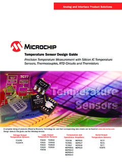
3 Protected by Patents including 5481178, 5705919, 5929620, 6100678, 6144194, 6177787, 5408150, 6580258, 6304066, 7420359, 8786268 Patent Pending. Licensed under Patent 7000125 and other related patents worldwide. LOAD CURRENT (A) (%)POWER LOSS (W) TA01b20809060029871465310100 VIN = 48 VVOUT = 12 VfSW = 150kHzEFFICIENCYPOWER LOSSE fficiency and Power Loss vs Load CurrentINTVCCTG0TG1 BOOST0 BOOST1SW0SW1BG0 FAULT MANAGEMENTTO/FROMOTHER ADI DEVICESSDASCLALERTRUN0 RUN1 EXTVCCVSENSE0+VSENSE0 F1 F220pF10nF10nFVOUT112V15A530 F530 F3886 TA01a4700pFVOUT05V15A2200pF*SOME DETAILS OMITTED FOR +ISENSE1+ISENSE0 ISENSE1 PMBusINTERFACE10 F1 F5m 10 F2 VIN18V TO F1 FVINLTC3886*GNDVDD33 VDD25 IIN+IIN H1 F220pF++Document FeedbackLTC3886/ LTC3886 -12 Rev FFor more information OF CONTENTSF eatures ..1 Power Conversion ..1 Applications ..1 Typical Application .. 1 Table of Contents ..2 Absolute Maximum Ratings ..4 Order Information ..4 Pin Configuration.
4 4 Electrical Characteristics ..5 Typical Performance Characteristics ..10 Pin Functions ..13 Block Diagram .. 16 Overview ..16 Main Control Loop ..16 EEPROM ..17 Power-Up and Initialization ..17 Soft-Start ..18 Time-Based Sequencing ..18 Event-Based Sequencing ..19 Shutdown ..19 Light-Load Current Operation ..20 PWM Loop Compensation ..20 Switching Frequency and Phase ..20 Output Voltage Sensing ..21 Output Current Sensing ..21 Input Current Sensing ..21 PolyPhase Load Sharing ..22 External/Internal Temperature Sense ..22 RCONFIG (Resistor Configuration) Pins ..23 Fault Handling ..23 Status Registers and ALERT Masking ..24 Mapping Faults to FA U LT Pins ..26 Power Good Pins ..26 CRC Protection ..26 Serial Interface ..26 Communication Protection ..27 Device Addressing ..27 Responses to VOUT and IOUT Faults ..27 Output Overvoltage Fault Response ..27 Output Undervoltage Response ..28 Peak Output Overcurrent Fault Response ..28 Responses to Timing Faults.
5 28 Responses to VIN OV Faults ..28 Responses to OT/UT Faults ..28 Internal Overtemperature Fault/Warn Response ..28 External Overtemperature and Undertemperature Fault Response ..29 Responses to External Faults ..29 Fault Logging ..29 Bus Timeout Protection ..29 Similarity Between PMBus, SMBus and I2C 2-Wire Interface ..30 PMBus Serial Digital Interface ..30 PMBus Command Summary ..35 PMBus Commands ..35*Data Format ..40 Applications Information ..41 Current Limit Programming ..41 ISENSE+ and ISENSE Pins ..41 Low Value Resistor Current Sensing ..42 Inductor DCR Current Sensing ..43 Slope Compensation and Inductor Peak Current ..44 Inductor Value Calculation ..44 Inductor Core Selection ..45 Power MOSFET and Optional Schottky Diode Selection ..45 CIN and COUT Selection ..46 Variable Delay Time, Soft-Start and Output Voltage Ramping ..46 Digital Servo Mode ..47 Soft Off (Sequenced Off) ..48 INTVCC Regulator ..49 Topside MOSFET Driver Supply (CB, DB).
6 50 Undervoltage Lockout ..50 Fault Indications ..50 LTC3886 / LTC3886 -13 Rev FFor more information OF CONTENTSOpen-Drain Pins ..51 Phase-Locked Loop and Frequency Synchronization ..51 Minimum On-Time Temperature Sense ..52 Derating EEPROM Retention at Temperature ..53 Input Current Sense Amplifier ..54 External Resistor Configuration Pins (RCONFIG) ..54 Voltage Selection ..54 Frequency Selection ..55 Phase Selection ..56 Address Selection Using RCONFIG ..56 Efficiency Considerations ..56 Programmable Loop Compensation ..57 Checking Transient Response ..58 PolyPhase Configuration ..59PC Board Layout Checklist ..59PC Board Layout Debugging ..62 Design Example ..63 Additional Design Checks ..65 Connecting the USB to I2C/SMBus/PMBus Adapter to the LTC3886 In System ..65 LTpowerPlay: An Interactive GUI for Digital Power . 66 PMBus Communication and Command Processing 67 PMBus Command Details ..69 Addressing and Write Protect ..69 General Configuration COMMANDS.
7 71On/Off/Margin ..72ON_OFF_CONFIG ..73 PWM Configuration ..74 Voltage ..78 Input Voltage and Limits ..78 Output Voltage and Limits ..79 For EnableMfrVoffThreshold = EnableMfrVoffThreshold = 82 Output Current and Limits ..82 Input Current and Limits ..84 Temper atur e ..85 External Temperature ..86 Timing On Sequence/Ramp ..86 Timing Off Sequence/Ramp ..87 Precondition for Restart ..88 Fault Response ..88 Fault Responses All Faults ..88 Fault Responses Input Voltage ..89 Fault Responses Output Voltage ..89 Fault Responses Output Current ..92 Fault Responses IC Temperature ..93 Fault Responses External Temperature ..94 Fault Sharing ..95 Fault Sharing Propagation ..95 Fault Sharing Response ..97 Scratchpad ..97 Identification ..98 Fault Warning and Status ..99 Telemetry ..106 EEPROM Memory Commands ..110 Store/Restore ..110 Fault Logging ..111 Fault Log Operation ..111 Block Memory Applications ..117 Package Description ..120 Revision History.
8 121 Typical Application ..122 Related Parts ..122 LTC3886 / LTC3886 -14 Rev FFor more information CONFIGURATIONABSOLUTE MAXIMUM RATINGSVIN, IIN+, IIN .. to 65 VTop Gate Transient Voltage (TG0, TG1) .. to 71 VBOOST0, BOOST1 .. to 71 VSwitch Transient Voltage (SW0, SW1) .. 5V to 65 VINTVCC, BG0, BG1, (BOOST0 SW0),(BOOST1 SW1) .. to 6 VVSENSE0+, VSENSE1+, ISENSE0+, ISENSE1+, ISENSE0 , ISENSE1 , EXTVCC .. to 15 VVSENSE0 .. to , SDA, SCL, ALERT .. to , VOUTn_CFG, FREQ_CFG, PHAS_CFG, VDD25 .. to (VIN IINP), (VIN IINM) .. to , PGOOD1, FA U LT, SHARE_CLK, ITH0, ITH1, ITHR0, ITHR1, VDD33, WP, TSNS0, TSNS1 , SYNC .. to (EXTVCC VIN) .. Peak Output Current ..100mAOperating Junction Temperature Range (Notes 2, 15, 16) .. 40 C to 125 C* Storage Temperature Range .. 65 C to 150 C*(Note 1)1615171819 TOP VIEW53 GNDUKG PACKAGEVARIATION: UKG52(46)52-LEAD (7mm 8mm) PLASTIC QFNTJMAX = 125 C, JA = 31 C/W, JC = 2 C/W EXPOSED PAD (PIN 53) IS GND, MUST BE SOLDERED TO PCB20212223242526525048 47 4644 43 423335393638408765421SW0TG0 ISENSE0+ISENSE0 TSNS0 VSENSE0+VSENSE0 ISENSE1+ISENSE1 ITHR0 ITH0 SYNCSCLBOOST1SW1TG1 TSNS1 VSENSE1+PGOOD0 PGOOD1 ITHR1 ITH1 VDD33 SHARE_CLKWPVDD25 BOOST0BG0 VINIIN+IIN INTVCCEXTVCCBG1 SDAALERTFAULT0 FAULT1 RUN0 RUN1 ASEL0 ASEL1 VOUT0_CFGVOUT1_CFGFREQ_CFGPHAS_CFG323130 2827910111213143429 ORDER INFORMATIONLEAD FREE FINISHTAPE AND REELPART MARKING*PACKAGE DESCRIPTIONTEMPERATURE RANGELTC3886 EUKG#PBFLTC3886 EUKG#TRPBFLTC3886 UKG52-Lead (7mm 8mm) Plastic QFN 40 C to 125 CLTC3886 IUKG#PBFLTC3886 IUKG#TRPBFLTC3886 UKG52-Lead (7mm 8mm) Plastic QFN 40 C to 125 CLTC3886 EUKG-1#PBFLTC3886 EUKG-1#TRPBFLTC38861 UKG52-Lead (7mm 8mm) Plastic QFN 40 C to 125 CLTC3886 IUKG-1#PBFLTC3886 IUKG-1#TRPBFLTC38861 UKG52-Lead (7mm 8mm)
9 Plastic QFN 40 C to 125 CContact the factory for parts specified with wider operating temperature ranges. *The temperature grade is identified by a label on the shipping and reel specifications. Some packages are available in 500 unit reels through designated sales channels with #TRMPBF suffix.* See Derating EEPROM Retention at Temperature in the Applications Information section for junction temperatures in excess of 125 : Pins omitted to achieve high input voltage FFor more information CHARACTERISTICS The l denotes the specifications which apply over the specified operating junction temperature range, otherwise specifications are at TJ = 25 C (Note 2). VIN = 16V, EXTVCC = 0V, VRUN0 = , VRUN1 = fSYNC = 350kHz (externally driven), and all programmable parameters at factory default unless otherwise VoltageVINI nput Voltage Range(Note 12) Voltage Supply Current Normal Operation (Note 14) VRUN = , No Caps on TG and BG VRUN = 0V 26 22 mA mAVUVLOU ndervoltage Lockout Threshold When VIN > Falling VINTVCC VTINITI nitialization TimeDelay from RESTORE_USER_ALL, MFR_REST, or VINTVCC > VUVLO Until TON_DELAY Can Begin35msControl LoopVOUTR0 Range 0 Maximum VOUT Range 0 Set Point Accuracy Range 0 Resolution Range 0 LSB Step Size, FSR = VOUT (Notes 9, 10) l 12 4 % Bits mVVOUTR1 Range 1 Maximum VOUT Range 1 Set Point Accuracy Range 1 Resolution Range 1 LSB Step Size, FSR = VOUT (Notes 9, 10) l 12 2 % Bits mVVLINEREGLine Regulation16V < VIN < 60Vl Regulation VITH = VITH = l %gm0,1 Resolution3bitsError Amplifier gm(MAX)
10 ITH = Amplifier gm(MIN)ITH = Amplifier gm LSB Step SizeITH = ,1 Resolution5bitsCompensation Resistor RITHR(MAX)62k Compensation Resistor RITHR(MIN)0k IISENSEI nput CurrentVISENSE = 14Vl 1 2 AVI(lLIMIT)Resolution 3bitsVILIM(MAX)Hi Range Lo Rangel l68 4475 5082 56mV mVVILIM(MIN)Hi Range Lo 25mV mVGate DriverTG tr tfTG Transition Time: Rise Time Fall Time(Note 4) CLOAD = 3300pF CLOAD = 3300pF 30 30 ns nsBG tr tfBG Transition Time: Rise Time Fall Time(Note 4) CLOAD = 3300pF CLOAD = 3300pF 20 20 ns nsTG/BG t1 DTop Gate Off to Bottom Gate On Delay Time(Note 4) CLOAD = 3300pF10nsBG/TG t2 DBottom Gate Off to Top Gate On Delay Time(Note 4) CLOAD = 3300pF30nstON(MIN)Minimum On-Time90nsLTC3886/ LTC3886 -16 Rev FFor more information CHARACTERISTICS The l denotes the specifications which apply over the specified operating junction temperature range, otherwise specifications are at TJ = 25 C (Note 2).