Transcription of LTC4417 - Prioritized PowerPath Controller
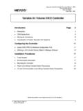
1 LTC441714417fTypical applicaTion FeaTuresDescripTionPrioritized PowerPath ControllerThe LT C 4417 connects one of three valid power supplies to a common output based on priority. Priority is defined by pin assignment, with V1 assigned the highest priority and V3 the lowest priority. A power supply is defined as valid when its voltage has been within its overvoltage (OV) and undervoltage (UV) window continuously for at least 256ms. If the highest priority valid input falls out of the OV/UV window, the channel is immediately disconnected and the next highest priority valid input is connected to the common output. Tw o or more LTC4417s can be cascaded to provide switchover between more than three LTC4417 incorporates fast non-overlap switching circuitry to prevent both reverse and cross conduction while minimizing output droop.
2 The gate driver includes a 6V clamp to protect external MOSFETs. A controlled output ramp feature minimizes start-up inrush current. Open drain VALID outputs indicate the input supplies have been within their OV/UV window for , LT, LT C, LT M, Linear Technology and the Linear logo are registered trademarks and PowerPath , ThinSOT and Hot Swap are trademarks of Linear Technology Corporation. All other trademarks are the property of their respective Switching from 12V V1 to V2applicaTionsn Selects Highest Priority Supply from Three Inputsn Blocks Reverse and Cross Conduction Currentsn Wide Operating Voltage Range: to 36Vn 42V Protection Against Reverse Battery Connectionn Fast Switchover Minimizes Output Voltage Droopn Low 28 A Operating Currentn <1 A Current Draw from Supplies Less than VOUTn Input Overvoltage/Undervoltage Protectionn Adjustable Overvoltage/Undervoltage Hysteresisn P-Channel MOSFET Gate Protection Clampn Cascadable for Additional Input Suppliesn 24-Lead Narrow SSOP and 4mm 4mm QFN Packagesn Industrial Handheld Instrumentsn High Availability Systemsn Battery Backup Systemsn Servers and Computer PeripheralsIRF7324 IRF7324 IRF7324VS1V1 VOUTVALID1 VALID2 VALID3V1: 12V WALL ADAPTER2 AOUTPUTV2: Li-IonMAIN/SWAPPABLEV3: 12V = 0V, IL = 2 ACL = 120 F50ms/DIV4417 TA01b2V/DIVVOUTV1 UV MaxiMuM raTingsSupply Voltages V1, V2, V3.
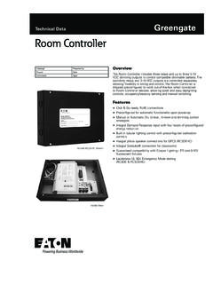
3 42V to 42V VOUT, VS1, VS2, VS3 .. to 42 VVoltage from V1, V2, V3 to VOUT .. 84V to 42 VVoltage from VS1, VS2, VS3 to G1, G2, G3 .. to 7. 5 VInput Voltages EN, SHDN .. to 42V OV1, OV2, OV3, UV1, UV2, UV3 .. to 6V HYS .. to 1 VInput Currents OV1, OV2, OV3, UV1, UV2, UV3, HYS .. 3mAOutput Voltages VALID1, VALID2, VALID3 .. to 42V CAS .. to 6 VOutput Currents VALID1, VALID2, VALID3, CAS ..2mAOperating Ambient Temper atur e Range LTC4 417C ..0 C to 70 C LTC4 40 C to 85 C LTC4 417H .. 40 C to 125 CStorage Temper atur e Range .. 65 C to 150 CLead Temper atur e GN Package (Soldering, 10 sec) ..300 C(Notes 1, 2)123456789101112 TOP VIEWGN PACKAGE24-LEAD NARROW PLASTIC SSOP242322212019181716151413 ENSHDNHYSUV1OV1UV2OV2UV3OV3 VALID1 VALID2 VALID3V1V2V3VS1G1VS2G2VS3G3 VOUTCASGND TJMAX = 150 C, JA = 85 C/W, JC = 30 C/W24232221201978925UF PACKAGE24-LEAD (4mm 4mm) PLASTIC QFN101112654321131415161718UV1OV1UV2OV2U V3OV3VS1G1VS2G2VS3G3 HYSSHDNENV1V2V3 VALID1 VALID2 VALID3 GNDCASVOUT TJMAX = 150 C, JA = 47 C/W, JC = C/W EXPOSED PAD (PIN 25)
4 PCB GND CONNECTION OPTIONALpin conFiguraTionorDer inForMaTionLEAD FREE FINISHTAPE AND REELPART MARKING*PACKAGE DESCRIPTIONTEMPERATURE RANGELTC4417 CGN#PBFLTC4417 CGN#TRPBFLTC4417GN24-Lead Narrow Plastic SSOP0 C to 70 CLTC4417 IGN#PBFLTC4417 IGN#TRPBFLTC4417GN24-Lead Narrow Plastic SSOP 40 C to 85 CLTC4417 HGN#PBFLTC4417 HGN#TRPBFLTC4417GN24-Lead Narrow Plastic SSOP 40 C to 125 CLTC4417 CUF#PBFLTC4417 CUF#TRPBF441724-Lead (4mm 4mm) Plastic QFN0 C to 70 CLTC4417 IUF#PBFLTC4417 IUF#TRPBF441724-Lead (4mm 4mm) Plastic QFN 40 C to 85 CLTC4417 HUF#PBF LTC4417 HUF#TRPBF441724-Lead (4mm 4mm) Plastic QFN 40 C to 125 CConsult LT C Marketing for parts specified with wider operating temperature ranges. *The temperature grade is identified by a label on the shipping container. Consult LT C Marketing for information on non-standard lead based finish more information on lead free part marking, go to: For more information on tape and reel specifications, go to: characTerisTics The l denotes the specifications which apply over the full operating temperature range, otherwise specifications are at TA = 25 C.
5 For all tests, V1 = VS1, V2 = VS2, V3 = VS3. Unless otherwise noted, V1 = V2 = V3 = VOUT = 12V, HYS = ,VOUTV1 to V3,VOUT Operating Supply ,VOUT(EN)Total Supply Current with Channels Enabled V1 = 5V, V2 = 12V, V3 = , VOUT = 4V, (Notes 3, 4)l2878 AIV1-V3(EN)Total Supply Current with Channels DisabledV1 = 5V, V2 = 12V, V3 = , VOUT = EN = 0V, (Notes 3, 4)l3193 AIV1-V3(SHDN)Total Supply Current When ShutdownV1 = 5V, V2 = 12V, V3 = , VOUT = SHDN = 0V, (Notes 3, 4) A IVOUTVOUT Supply CurrentV1 = 5V, V2 = 12V, V3 = , VOUT = 4Vl1430 AIPRIORITYC urrent from Highest V1 to V3 Priority Input Source (V1)V1 = 5V, V2 = 12V, V3 = , VOUT = 4V V1 = 5V, V2 = 12V, V3 = , VOUT = EN = 0Vl 206 45 A AIHIGHESTC urrent from Highest V1 to V3 Voltage Input SourceV1 = 5V, V2 = 12V, V3 = , VOUT = 4V, (Note 3, 4)
6 L1172 AV1 = 5V, V2 = 12V, V3 = , VOUT = EN = 0V, SHDN = 0V, (Note 3, 4)l1580 AILOWERC urrent from V1 to V3 Input Voltage Sources Lower than VOUTV1 = 5V, V2 = 12V, V3 = , VOUT = 4V Not Highest Valid Priority AGate Control VGOpen (VS VG) Clamp VoltageVOUT = 11V, G1 to G3 = VG(SOURCE)Sourcing (VS VG) Clamp VoltageVOUT = 11V, I = 10 VG(SINK)Sinking (VS VG) Clamp VoltageVOUT = 11V, I = 10 VG(OFF)G1 to G3 Off (VS VG) ThresholdV1 = V2 = V3 = , VOUT = , G1 to G3 Rising VG(SLEW,ON)G1 to G3 Pull-Down Slew RateVOUT = 11V, CGATE = 10nF (Note 5)l4920V/ s VG(SLEW,OFF)G1 to G3 Pull-Up Slew RateVOUT = 11V, CGATE = 10nF (Note 6) sIG(DN)G1 to G3 Low Pull-Down CurrentVOUT = , V1 to V3 = , (G1 to G3) = VG + ARG(OFF)G1 to G3 OFF ResistanceVOUT = 4V, V1 to V3 = 5V, IG = 10mAl91626 VREVR everse Voltage ThresholdMeasure (V1 to V3) VOUT, VOUT Fallingl30120200mVtG(SWITCHOVER)Pin Break-Before-Make TimeVOUT = 11V, CGATE = 10nF, (Note 7) stpG(SHDN)G1 to G3 Turn-Off Delay From SHDNVOUT = 11V, Falling Edge SHDN to (G1 to G3) = (VS1 to VS3) 3V, CGATE = 10nFl2050100 stpG(EN,OFF)G1 to G3 Turn-Off Delay From ENVOUT = 11V, Falling EN Edge to (G1 to G3) = (VS1 to VS3) 3V, CGATE = stpG(EN,ON)G1 to G3 Turn-On Delay From ENVOUT = 11V, Rising EN Edge to (G1 to G3) = (VS1 to VS3) 3V, CGATE = sLTC441744417fNote 1: Stresses beyond those listed under Absolute Maximum Ratings may cause permanent damage to the device.
7 Exposure to any Absolute Maximum Rating condition for extended periods may affect device reliability and 2: All currents into device pins are positive; all currents out of device pins are negative. All voltages are referenced to GND unless otherwise 3: Each V1 to V3 supply current specification includes current into the corresponding VS1 to VS3 for the channel(s) being 4: Specification represents the total diode-ORed current of V1 to V3 input supplies, selecting the highest voltage as the input source. If two input supplies are similar in voltage and higher than the remaining input supply voltage, the current is split evenly between the two higher voltage supplies. Current is split evenly if all supplies are 5: Falling edge of G1 to G3 measured from 11V to 6: Rising edge of G1 to G3 measured from 7V to 7: UV1 driven below VOV,UV(THR).
8 Time is measured from respective rising edge G1 to G3 crossing (VS1 to VS3) 3V to next valid priority falling edge G1 to G3 crossing (VS1 to VS3) characTerisTics The l denotes the specifications which apply over the full operating temperature range, otherwise specifications are at TA = 25 C. For all tests, V1 = VS1, V2 = VS2, V3 = VS3. Unless otherwise noted, V1 = V2 = V3 = VOUT = 12V, HYS = PinsVVALID(OL)VALID1 to VALID3 Output Low VoltageI = 1mA, (V1 to V3) = , VOUT = (OFF)VALID1 to VALID3 Delay OFF From OV/UV Faultl5813 sVCAS(OH)CAS Output High VoltageI = 1 (OL)CAS Output Low VoltageI = Pull-Up CurrentSHDN = 0V, CAS = 1Vl 6 20 40 AtpCAS(EN)CAS Delay from VG(OFF)VOUT = sVEN(THR)EN Threshold VoltageEN Risingl (THR)SHDN Threshold VoltageSHDN Risingl (HYS)SHDN, EN Threshold Hysteresis100mVISHDN_ENSHDN, EN Pull-Up CurrentSHDN = EN = 0Vl 2 5 AILEAKSHDN, EN, VALID1 to VALID3, CAS Leakage Current SHDN = EN = (VALID1 to VALID3) = 36V, CAS = 1 AOV, UV Protection CircuitryVOV_UV(THR)OV1 to OV3, UV1 to UV3 Comparator Threshold VOUT = 11V, OV1 to OV3 Rising, UV1 to UV3 (HYS)
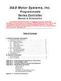
9 OV1 to OV3, UV1 to UV3 Comparator HysteresisVOUT = 11Vl153045mVIUV_OV(LEAK)OV1 to OV3, UV1 to UV3 Leakage CurrentOV1 to OV3 = , UV1 to UV3 = 20nAIOV_UV(MIN)Minimum External Hysteresis CurrentIHYS = 400nAl355075nAIOV_UV(MAX)Maximum External Hysteresis CurrentIHYS = 4 Al420520620nAVHYSHYS VoltageIHYS = 4 Al470495520mVtVALIDV1 to V3 Validation Time100256412msLTC441754417fTypical perForMance characTerisTics VG vs TemperatureGate Falling Slew Rate vs TemperatureGate Rising Slew Rate vs TemperatureIG(DN) vs TemperatureSwitchover Time vs TemperatureValid Delay Off Time vs TemperatureTotal Shutdown Supply Current vs Supply VoltageTotal Enabled Supply Current vs Supply VoltageIV1-V3,VOUT(EN) vs Supply VoltageSUPPLY VOLTAGE (V)0 TOTAL ENABLE SUPPLY CURRENT ( A)40352530201015501020304417 G0240 ALL SUPPLY, VS AND VOUTPINS CONNECTED TOGETHERSUPPLY VOLTAGE (V)0 TOTAL SHUTDOWN SUPPLY CURRENT ( A)25201015501020304417 G0140 ALL SUPPLY AND VS PINS CONNECTEDTOGETHER, VOUT = 0 VTEMPERATURE ( C) 50 VG (V) 25251004417 G0412575 TEMPERATURE ( C) 50IG(DN) ( A) 25251004417 G0712575 TEMPERATURE ( C) 50tG(SWITCHOVER) ( s) 25251004417 G0812575 TEMPERATURE ( C) 50 VALID DELAY TIME ( s) 25251004417 G0912575 TEMPERATURE ( C) 50 GATE FALLING SLEW RATE (V/ s)1614101284620050 25251004417 G0512575V1 = = 5VV1 = 12VV1 = 36 VCGATE = 10nFV1 = V2 = V3V1 = 24 VTEMPERATURE ( C) 50 GATE RISING SLEW RATE (V/ s)1612480050 25251004417 G0612575V1 = = 5VV1 = 12V, 24V, 36VV1 = V2 = V3 CGATE = 10nFV2 = VS2 VOLTAGE (V)0IV1-V3,VOUT(EN) ( A)
10 16141012846201020304417 G0340V1 = VS1 = 5VV2 = VS2V3 = VS3 = = perForMance characTerisTicsVOUT Switching from Higher to Lower VoltageVOUT Switching from Lower to Higher Voltage with Slew Rate Control CircuitryReverse Voltage BlockingVVALID(OL) vs Pull-Up CurrentVOV,UV vs TemperatureDeglitched Connectionpin FuncTionsCAS: Cascade Output. Digital output used for cascad-ing multiple LTC4417s. Connect CAS to EN of another LTC4417 to increase the number of multiplexed input supplies. CAS is pulled up to the internal VLDO voltage by an internal 20 A current source to indicate when all inputs are invalid, the external P-channel MOSFETs are determined to be off, and EN is above 1V. CAS also pulls high when SHDN is driven below 1V. CAS is pulled low when any input supply is within the OV/UV window for at least 256ms and both SHDN and EN are above 1V.