Transcription of LTC5800-IPM - SmartMesh IP Node 2.4GHz …
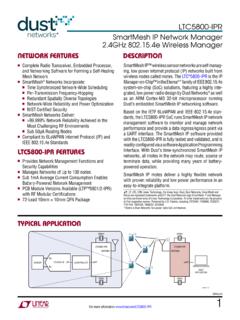
1 LTC5800-IPM15800ipmfaFor more information applicaTion neTwork FeaTuresDescripTionSmartMesh IP Node Wireless Mote-on-ChipSmartMesh IP wireless sensor networks are self manag-ing, low power internet protocol (IP) networks built from wireless nodes called motes. The LT C 5800-IPM is the IP mote product in the Eterna * family of IEEE System-on-Chip (SoC) solutions, featuring a highly-integrated, low power radio design by Dust Networks as well as an ARM Cortex-M3 32-bit microprocessor running Dust s embedded SmartMesh IP networking LTC5800-IPM SoC features an on-chip power ampli-fier (PA) and transceiver, requiring only power supply decoupling, crystals, and antenna with matching circuitry to create a complete wireless Dust s time-synchronized SmartMesh IP networks, all motes in the network may route, source or terminate data, while providing many years of battery powered operation. The SmartMesh IP software provided with the LTC5800-IPM is fully tested and validated, and is read-ily configured via a software Application Programming IP motes deliver a highly flexible network with proven reliability and low power performance in an easy-to-integrate , LT, LT C, LT M, Linear Technology, the Linear logo, Dust, Dust Networks, SmartMesh and Eterna are registered trademarks and LTP, the Dust Networks logo, SmartMesh IP and Mote-on-Chip are trademarks of Linear Technology Corporation.
2 All other trademarks are the property of their respective owners. Protected by Patents, including 7375594, 7420980, 7529217, 7791419, 7881239, 7898322, 8222965. * Eterna is Dust Networks low power radio SoC FeaTures nComplete Radio Transceiver, Embedded Processor, and Networking Software for Forming a Self-Healing Mesh Network nSmartMesh Networks Incorporate: nTime Synchronized Network-Wide Scheduling nPer Transmission Frequency Hopping nRedundant Spatially Diverse Topologies nNetwork-Wide Reliability and Power Optimization nNIST Certified Security nSmartMesh Networks Deliver n> Network Reliability Achieved in the Most Challenging RF Environments nSub 50 A Routing Nodes nCompliant to 6 LoWPAN Internet Protocol (IP) and IEEE Standards nIndustry-Leading Low Power Radio Technology to Receive a Packet to Transmit at 8dBm nPCB Module Versions Available (LTP5901/ LTP5902-IPM) with RF Modular Certifications , IEEE System-on-Chip n72-Pin 10mm 10mm QFN Package nMicrium COS-II Real Time Operating System based On-Chip Software Development Kit5800 IPM TA0120 MHz CONTROLLERSENSORIN+IN SPILTC2379-1832kHzLTC5800-IPMUARTANTENNA 20 MHz32kHzLTC5800-IPRUARTANTENNAHOSTAPPLIC ATIONLTC5800-IPM25800ipmfaFor more information oF conTenTs Network Features.
3 1 LTC5800-IPM Features ..1 Typical Application .. 1 SmartMesh Network Overview ..3 Absolute Maximum Ratings ..4 Order Information ..4 Pin Configuration ..4 Recommended Operating Conditions ..5DC Characteristics ..5 Radio Specifications ..5 Radio Receiver Characteristics ..6 Radio Transmitter Characteristics ..6 Digital I/O Characteristics ..7 Temperature Sensor Characteristics ..7 Analog Input Chain Characteristics ..7 System Characteristics ..8 UART AC Characteristics ..8 TIMEn AC Characteristics ..9 Radio_Inhibit AC Characteristics ..10 Flash AC Characteristics ..10 Flash SPI Slave AC Characteristics ..11 SPI Master AC Characteristics ..12I2C AC Characteristics ..13 Typical Performance Characteristics ..15 Pin Functions .. 26 Power Supply ..26 Supply Monitoring and Reset ..27 Precision Timing ..27 Application Time Synchronization ..27 Time References ..27 Radio ..28UA RTs ..28 Autonomous MAC ..29 Security ..29 Temperature Sensor.
4 30 Radio Inhibit ..30 Flash Programming ..30 FLASH Data Retention ..30 State Diagram ..30 SPI Master ..32I2C Master ..331-Wire Master ..33 Applications Information ..33 Modes of Operation ..33 Slave Mode ..33 Master Mode ..33On-Chip SDK (OCSDK) ..33 Regulatory and Standards Compliance ..34 Soldering Information ..34 Related Documentation ..35 Package Description ..36 Revision History ..37 Typical Application ..38 Related Parts ..38 LTC5800-IPM35800ipmfaFor more information neTwork overviewThe Network Manager uses health reports to continually optimize the network to maintain > data reliability even in the most challenging RF use of TSCH allows SmartMesh devices to sleep in between scheduled communications and draw very little power in this state. Motes are only active in time slots where they are scheduled to transmit or receive, typically resulting in a duty cycle of < 1%. The optimization soft-ware in the Network Manager coordinates this schedule automatically.
5 When combined with the Eterna low power radio, every mote in a SmartMesh network even busy routing ones can run on batteries for years. By default, all motes in a network are capable of routing traffic from other motes, which simplifies installation by avoiding the complexity of having distinct routers vs non-routing end nodes. Motes may be configured as non-routing to further reduce that particular mote s power consumption and to support a wide variety of network SmartMesh network consists of a self-forming multi-hop mesh of nodes, known as motes, which collect and relay data, and a network manager that monitors and manages network performance and security, and exchanges data with a host application. SmartMesh networks communicate using a time slotted channel hopping (TSCH) link layer, pioneered by Dust Networks. In a TSCH network, all motes in the network are synchronized to within less than a millisecond. Time in the network is organized into time slots, which enables collision-free packet exchange and per-transmission channel-hopping.
6 In a SmartMesh network, every device has one or more parents ( mote 3 has motes 1 and 2 as parents) that provide redundant paths to overcome communications interruption due to interference, physical obstruction or multi-path fading. If a packet transmission fails on one path, the next retransmission may try on a different path and different RF channel. A network begins to form when the network manager instructs its on-board Access Point (AP) radio to begin sending advertisements packets that contain information that enables a device to synchronize to the network and request to join. This message exchange is part of the secu-rity handshake that establishes encrypted communications between the manager or application, and mote. Once motes have joined the network, they maintain synchronization through time corrections when a packet is the heart of SmartMesh motes and network manag-ers is the Eterna IEEE System-on-Chip (SoC), featuring Dust Networks highly integrated, low power radio design, plus an ARM Cortex-M3 32-bit micropro-cessor running SmartMesh networking software.
7 The SmartMesh networking software comes fully compiled yet is configurable via a rich set of Application Program-ming Interfaces (APIs) which allows a host application to interact with the network, to transfer information to a device, to configure data publishing rates on one or more motes, or to monitor network state or performance metrics. Data publishing can be uniform or different for each device, with motes being able to publish infrequently or faster than once per second as ongoing discovery process ensures that the network continually discovers new paths as the RF conditions change. In addition, each mote in the network tracks per-formance statistics ( quality of used paths, and lists of potential paths) and periodically sends that information to the network manager in packets called health reports. ALL NODES ARE CAN TRANSMIT AND NEW NODE CAN JOINANYWHERE BECAUSE ALLNODES CAN 02 HOSTAPPLICATIONAPSNO 01 NETWORK MANAGERMote2 Mote1 Mote3 LTC5800-IPM45800ipmfaFor more information conFiguraTionabsoluTe MaxiMuM raTingsSupply Voltage on V SUPPLY.
8 Voltage on AI_0/1/2/3 Inputs .. on Any Digital I/O Pin .. to VSUPPLY + RF Level ..10dBmStorage Temper atur e Range (Note 3) .. 55 C to 125 CJunction Temper atur e (Note 3) ..125 COperating Temper atur e Range LTC5800I .. 40 C to 85 C LTC5800H .. 55 C to 105 CCAUTION: This part is sensitive to electrostatic discharge (ESD). It is very important that proper ESD precautions be observed when handling the LTC5800-IPM .(Note 1)TOP VIEWWR PACKAGE72-LEAD PLASTIC QFNRADIO_INHIBIT 1 CAP_PA_1P 2 CAP_PA_1M 3 CAP_PA_2M 4 CAP_PA_2P 5 CAP_PA_3P 6 CAP_PA_3M 7 CAP_PA_4M 8 CAP_PA_4P 9 VDDPA 10 LNA_EN / GPIO17 11 RADIO_TX / GPIO18 12 RADIO_TXn / GPIO19 13 ANTENNA 14AI_0 15AI_1 16AI_3 17AI_2 18 OSC_32K_XOUT 19 OSC_32K_XIN 20 VBGAP 21 RESETn 22 TDI 23 TDO 24 TMS 25 TCK 26DP4 (GPIO23) 27 OSC_20M_XIN 28 OSC_20M_XOUT 29 VDDA 30 VCORE 31 VOSC 32DP3 (GPIO22) / TIMER8_IN 33DP2 (GPIO21) / LPTIMER_IN 34 SLEEPn / GPIO14 35DP0 (GPIO0) / SPIM_SS_2n 3654 VPP53 SPIS_SSn / SDA52 SPIS_SCK / SCL51 SPIS_MOSI / GPIO26 / UARTC1_RX50 SPIS_MISO / 1_WIRE / UARTC1_TX49 PWM0 / GPIO1648 DP1 (GPIO20) / TIMER16_IN47 SPIM_SS_0n / GPIO1246 SPIM_SS_1n / GPIO1345 IPCS_SSn / GPIO344 IPCS_SCK / GPIO443 SPIM_SCK / GPIO942 IPCS_MOSI / GPIO541 SPIM_MOSI / GPIO1040 IPCS_MISO / GPIO639 SPIM_MISO / GPIO1138 UARTCO_RX37 UARTCO_TXEXPOSED PAD(GND)
9 72 TIMEn71 UART_TX70 UART_TX_CTSn69 UART_TX_RTSn68 UART_RX67 UART_RX_CTSn66 UART_RX_RTSn65 VSUPPLY64 CAP_PRIME_1P63 CAP_PRIME_1M62 CAP_PRIME_2M61 CAP_PRIME_2P60 CAP_PRIME_3P59 CAP_PRIME_3M58 CAP_PRIME_4M57 CAP_PRIME_4P56 VPRIME55 FLASH_P_ENn TJMAX = 125 C, JA = 21 C/W, JCbottom = C/W EXPOSED PAD IS GND, MUST BE SOLDERED TO PCBorDer inForMaTionLEAD FREE FINISHTAPE AND REELPART MARKING*PACKAGE DESCRIPTIONTEMPERATURE RANGELTC5800 IWR-IPMA#PBFLTC5800 IWR-IPMA#PBFLTC5800WR-IPMA72-Lead (10mm 10mm ) Plastic QFN 40 C to 85 CLTC5800 HWR-IPMA#PBF LTC5800 HWR-IPMA#PBF LTC5800WR-IPMA72-Lead (10mm 10mm ) Plastic QFN 55 C to 105 C*The temperature grade is identified by a label on the shipping more information on lead free part marking, go to: This product is only offered in trays. For more information go to: Some packages are available in 500 unit reels through designated sales channels with #TRMPBF functions shown in italics are currently not supported in more information operaTing conDiTions The l denotes the specifications which apply over the full operating temperature range, otherwise specifications are at TA = 25 C and VSUPPLY = unless otherwise VoltageIncluding Noise and Load Regulationl NoiseRequires Recommended RLC Filter, 50Hz to 2 MHzl250mVOperating Relative HumidityNon-condensingl1090% RHTemperature Ramp RateWhile Operating in Networkl 8+8 C/min Dc characTerisTics The l denotes the specifications which apply over the full operating temperature range, otherwise specifications are at TA = 25 C and VSUPPLY = unless otherwise Power-on APower-on ResetDuring Power-on Reset, Maximum 750 s + VSUPPLY Rise Time from 1V to on, ARM Cortex-M3, Flash, Radio, and Peripherals Off, All Data and State Retained.
10 Reference ADeep SleepRAM on, ARM Cortex-M3, Flash, Radio, and Peripherals Off, All Data and State Retained, Reference AIn-Circuit ProgrammingRESETn and FLASH_P_ENn Asserted, IPCS_SCK @ 8 MHz20mAPeak Operating Current +8dBm +0dBmSystem Operating at , Radio Transmitting, During Flash Write. Maximum duration ms. 30 26 mA mAActiveARM Cortex M3, RAM and Flash Operating, Radio and All Other Peripherals Off. Clock Frequency of CPU and Peripherals Set to , VCORE = WriteSingle Bank Flash EraseSingle Bank Page or Mass Tx +0dBm (LTC5800I) +0dBm (LTC5800H) +8dBm (LTC5800I) +8dBm (LTC5800H)Current With Autonomous MAC Managing Radio Operation, CPU Inactive. Clock Frequency of CPU and Peripherals Set to mA mA mA mARadio Rx LTC5800I LTC5800 HCurrent With Autonomous MAC Managing Radio Operation, CPU Inactive. Clock Frequency of CPU and Peripherals Set to mA mAraDio speciFicaTions The l denotes the specifications which apply over the full operating temperature range, otherwise specifications are at TA = 25 C and VSUPPLY = unless otherwise of Channelsl15 Channel Separationl5 MHzChannel Center FrequencyWhere k = 11 to 25, as Defined by + 5 (k-11)MHzRaw Data Ratel250kbpsAntenna Pin ESD ProtectionHBM Per JEDEC JESD22-A114F 1000 VRange (Note 4) Indoor Outdoor Free Space25 C, 50% RH, +2dBi Omni-Directional Antenna, Antenna 2m Above Ground 100 300 1200 m m m LTC5800-IPM65800ipmfaFor more information receiver characTerisTics The l denotes the specifications which apply over the full operating temperature range, otherwise specifications are at TA = 25 C and VSUPPLY = unless otherwise SensitivityPacket Error Rate (PER) = 1% (Note 5)