Transcription of Mark II Series Molded Plastic Manometers
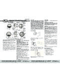
1 Bulletin D-58. Mark II Series Molded Plastic Manometers Specifications - Installation and Operating Instructions 1-7/16 3-11/16. 1-1/4 [ ] [ ] 7/32 [ ] HOLE. 5/8. [ ] [ ]. 5-29/32. 4-25/32 [ ]. [ ]. 25/32 4-23/32. [ ] [ ]. 1-1/8. [ ] 25/32 [ ] 7/32 X 13/32. 7-13/32 [ ] [ X ]. 2-1/4 MOUNTING SLOT. [ ] MAX. Mark II Model No. 25 inclined-vertical manometer, (shown with optional A-612 portable stand). dwyer Mark II Manometers come in a variety of ranges. Make SPECIFICATIONS. sure the fluid being used is for the correct manometer. Accuracy: 3% FS. Temperature Limits: 140 F (60 C). Pressure Limits: 10 psi (70 kPa). Mark II #25, 27, MM-80 and M-700 Pa use red gage fluid Weight: lb (472 g). (specific gravity ). Mark II #26, 28 and MM180 use blue gage fluid (specific gravity MAINTENANCE. ). Check fluid level regularly and adjust zero with zero adjust knob. Be sure tubing connections are disconnected and gage is open If additional fluid is required, call, fax or email the dwyer office to atmosphere before adjusting zero.
2 Listed at bottom of page. Clean with mild soap and water. Avoid any cleaning fluids which INSTALLATION may result in damaging the gage. Position manometer on a vertical surface. Drill two 1/8 or 9/64 . holes on a vertical line 3-15/16 apart. Loosely mount ACCESSORIES. manometer with self-tapping screws provided. Adjust gage until Each Mark II manometer includes two tubing connectors for 1/8 . level bubble is centered in level vial, then secure the manometer pipe or sheet metal ducts, two mounting screws, 1 oz. bottle of tightly. indicating fluid, red and green pointer flags, 8 of double column tubing and instructions. For portable use, order optional A-612 Portable Stand. FILLING. Turn the zero set knob counterclockwise until it stops, then turn Model Range Fluid Used clockwise 3 full turns. This puts zero in approximately the middle Mark II 25 0-3 in Red fluid.
3 826 of the travel adjustment in either direction. Remove the fill plug Mark II 26 0-7 in Blue oil, and fill with gage fluid until fluid reaches zero on scale. Minor Mark II 27* 0-7000 fpm Red fluid, .826 adjustments can be made to adjust zero by adjusting zero knob. Mark II MM-80 0-80 mm Red fluid, .826 Replace fill plug. If gage is overfilled, remove excess by inserting Mark II M-700PA 10-0-700 Pa Red fluid, .826 pipe cleaner through the fill port to blot up excess fluid. dwyer INSTRUMENTS, INC. Phone: 219/879-8000 BOX 373 MICHIGAN CITY, INDIANA 46360, Fax: 219/872-9057 e-mail: APPLICATIONS MARK II MANOMETER. PITOT TUBE. (SECTION. ENLARGED. TO SHOW. DETAIL). Pt Ps FLOW. PITOT TUBE SENSES TOTAL AND STATIC PRESSURES. MANOMETER. MEASURES VELOCITY PRESSURE-(DIFFERENCE BETWEEN TOTAL AND. AIR FILTER GAGE STATIC PRESSURES). Mount gage within 3 ft. of filter bank.
4 Install tubing adapters on each side of filter. Run tubing from clean side of filter to positive AIR VELOCITY CALCULATIONS: pressure side of gage (left fitting). Run downstream side to low pressure side of gage (right fitting). Install green and red arrows adjacent to indicating tube to indicate filter condition. Air Velocity = PV. D. AIR VELOCITY METER where Pv = velocity pressure in inches of water A pitot tube should be used for air velocity readings. Install the D = Air density in lb/ft3. pitot tube and gage carefully to ensure accuracy. Select a PB. location for the pitot tube with al least four diameters of smooth Air Density = x T. straight sections of duct both upstream and downstream. Install pitot tube in the center of duct with tip directed into air stream. where PB = Barometric Pressure in inches of mercury Connect the right angle (leg parallel to tip) to negative (right T = Absolute Temperature (indicated temperature F plus fitting) and straight pitot tube connection to positive (left 460).)
5 Connection) of gage. The velocity reading shown on the gage is the center or maximum velocity. For average velocity across the Flow in cu. ft. per min. = Duct area in square feet x air velocity full area, multiply by a factor of in ft. per min. No's. 27 and 28 require pitot tube at additional cost. See Bulletin F-41-F. The velocity indicated is for dry air at 70 F, barometric pressure and a resulting density of lb/ft3. For variation from these standard conditions, corrections may be based upon the following data. Bulletin D-58. Uso, Instalacion y Mantenimiento MANOMETROS dwyer MARK II. RANGOS. Modelo Rango Fluido 25 0~3 0,826 rojo 26 0~7 1,9 azul M-80 0~80 mm 0,826 rojo M-180 0~180 mm 1,9 azul M-700 Pa 10~0~700 Pascal 0,826 rojo 27 * 0~ 0,826 rojo 28 * 0~ 1,9 azul *Los modelos 27 y 28 requieren tubo Pitot, con costo adicional. INSTALACION Adjuste exactamente el cero del instrumento girando la perilla Instale el Mark II en una superficie vertical adecuada.
6 El seg n corresponda, y reponga el tap n de llenado. Si el ajuste ambiente debe estar libre de vapores de sustancias cloradas, o preciso es imposible por exceso de llenado, retire nuevamente solventes tales como benceno, acetona, tetracloruro de el tap n y extraiga el exceso introduciendo un limpiador de carbono, etc. El instrumento soporta presiones internas de tubos, que absorba el exceso. hasta 10 PSI, o 0,703 bar, y temperaturas de hasta 140 F . 60 C. NO EXCEDA ESTOS L MITES! Con el instrumento se suministra un tubo pl stico flexible doble de 2,4 m juntamente con adaptadores para conexi n a 1/8 NPT. Perfore dos orificios de 3,6 mm en l nea vertical, separados por Conecte el tubo marcado con una l nea roja al la entrada de alta 100mm, e instale el instrumento con los tornillos autorroscantes presi n mas elevada a sensar. Repita el procedimiento con el provistos con l.
7 Sin apretar demaslado, coloque el instrumento tubo restante en la entrada de baja presi n (LOW, a la derecha), vertical con ayuda del nivel incluido en la parte inferior derecha y a la presi n m s baja a sensar. del mismo. Verifique que ha quedado vertical y repita el proceso si es necesario. Para uso portable, use el soporte vertical tipo A- MANTENIMIENTO. 612. Verifique de tanto en tanto el nivel de fluido, y reajuste el cero del instrumento seg n sea necesario. Aseg rese de haber LLENADO venteado el instrumento desconectando los tubos de conexi n Gire en sentido antihorario la perilla de ajuste de cero hasta que a proceso (entradas HIGH y LOW en la parte superior del se detenga; g rela nuevamente pero en sentido horario unas man metro). Agregue fluido solo si es necesario, utilizando los tres vueltas, de modo de dejar la posibilidad de ajuste en fluidos dwyer azul o rojo seg n corresponda.
8 No utilice otros cualquier direcci n. Retire el tap n de llenado y comience a fluidos pues podr an da ar el material. Para limpieza use solo llenar el man metro lentamente hasta ver el l quido en las jab n neutro y agua, evitando solventes que puedan da ar el cercan as del cero de la escala. instrumento (vea Instalaci n). Limpie la perilla con un pincel peque o y suave. ATENCION: Use solamente fluido rojo de peso espec fico 0,826 para los modelos 25; 27; MM-80 y M-700Pa. Use solamente fluido azul de peso espec fico 1,9 para los modelos 26; 28 y MM-180. APLICACIONES MARK II MANOMETER. PITOT TUBE. (SECTION. ENLARGED. TO SHOW. DETAIL). Pt Ps FLOW. PITOT TUBE SENSES TOTAL AND STATIC PRESSURES. MANOMETER. MEASURES VELOCITY PRESSURE-(DIFFERENCE BETWEEN TOTAL AND. STATIC PRESSURES). MEDICI N DE TIRO MEDICION DE VELOCIDAD DE AIRE EN CONDUCTOS. Instale un tubo de hierro de 1/8 (3,2 mm) o mayor desde el Se requiere un tubo Pitot para esta aplicaci n.
9 inst lelo bien conducto a medir hasta una distancia de 1,5 m del instrumento. centrado dentro del conducto, en una zona donde sea recto y Use nicamente al conector derecho (LOW). Se debe prever la sin obstrucciones por lo menos en distancias de 4 di metros limpieza peri dica para evitar acumulaci n de suciedad. tanto corriente arriba como abajo del punto de inserci n. Aseg rese que la punta del tubo Pitot est bien dirigida hacia la INDICADOR DE PRESI N EST TICA corriente de aire. Conecte el tubo doble a los conectores HIGH. Tenga en cuenta que las velocidades de aire superiores a 100 y LOW, de modo de conectar LOW al conector en ngulo recto fpm (5 m/seg.) son una fuente de posibles errores en la del tubo Pitot, y el restante a HIGH. La velocidad le da es la medici n. Es conveniente usar sondas para presi n est tica. De m xima, correspondiente al centro del conducto.
10 Para calcular no ser disponibles, ingrese las conexiones al conducto, en la velocidad promedio multiplique por 0,9. Esta velocidad ngulo recto a la corriente de aire, y deles una terminaci n corresponde a aire seco, a 21 C a una presi n de 760 mmHg y suave en los extremos. de una densidad de 0,075 /cuft. Para otras condiciones se deben aplicar factores de correcci n de acuerdo a lo siguiente: INDICADOR DE OBSTRUCCI N DE FILTROS. Instale el man metro a distancia no mayor de 1 m del banco CALCULO DE VELOCIDAD DE AIRE. filtrante. Conecte el lado de descarga del filtro al conector LOW Velocidad de Aire =1096,2 (Pv/D). en la parte superior del instrumento y el otro tubo,al conector Donde Pv es la presi n por velocidad en de C. Agua. HIGH y a la presi n positiva. Retire el papel protector de la D: densidad del aire en #/pie3. flechas autoadhesivas (roja y verde)y adhi ralas adyacentes al tubo indicador para marcar lecturas de filtro limpio y sucio.