Transcription of MCP16301/MCP16301H Data Sheet - Microchip Technology
1 2011-2015 Microchip Technology 1 MCP16301/HFeatures Up to 96% Typical Efficiency Input Voltage Range: - to 30V (MCP16301)- to 36V (MCP16301H) Output Voltage Range: to 15V 2% Output Voltage Accuracy Qualification: AEC-Q100 Rev G, Grade 1 (-40 C to +125 C) Integrated N-Channel Buck switch : 460 m Minimum 600 mA Output current Over All Input Voltage Range (See Figure 2-6 for Maximum Output current vs. VIN):- up to 1A output current at , 5V and 12V VOUT, SOT-23 package at +25 C ambient temperature 500 kHz Fixed Frequency Adjustable Output Voltage Low Device Shutdown current Peak current Mode Control Internal Compensation Stable with Ceramic Capacitors Internal Soft-Start Cycle-by-Cycle Peak current Limit Undervoltage Lockout (UVLO): Overtemperature Protection Available Package.
2 SOT-23-6 Applications PIC Microcontroller and dsPIC Digital Signal Controller Bias Supply 24V Industrial Input DC-DC Conversion Set-Top Boxes DSL Cable Modems Automotive Wall Cube Regulation SLA Battery-Powered Devices AC-DC Digital Control Power Source Power Meters D2 Package Linear Regulator Replacement-See Figure 5-2 Consumer Medical and Health Care Distributed Power SuppliesGeneral DescriptionThe MCP16301/H devices are highly integrated, high -efficiency, fixed-frequency, step-down DC-DCconverters in a popular 6-pin SOT-23 package thatoperates from input voltage sources up to features include a high - side switch ,fixed-frequency peak current mode control, internalcompensation, peak current limit and overtemperatureprotection.
3 Minimal external components arenecessary to develop a complete step-down DC-DCconverter power supply. high converter efficiency is achieved by integrating thecurrent-limited, low-resistance, high -speed N-ChannelMOSFET and associated drive circuitry. Highswitching frequency minimizes the size of externalfiltering components, resulting in a small solution MCP16301/H devices can supply 600 mA ofcontinuous current while regulating the output voltagefrom to 15V. An integrated, high -performancepeak current mode architecture keeps the outputvoltage tightly regulated, even during input voltagesteps and output current transient conditions that arecommon in power EN input is used to turn the device on and turned off.
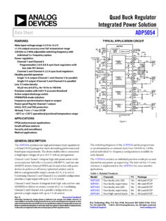
4 Only a few micro amps of current areconsumed from the input for power shedding and loaddistribution voltage is set with an external resistor MCP16301/H devices are offered in aspace-saving SOT-23-6 surface mount TypeMCP16301/H6-Lead SOT-23123456 SWVINENBOOSTGNDVFBHigh-Voltage Input Integrated switch Step-Down RegulatorMCP16301/HDS20005004D-page 2 2011-2015 Microchip Technology ApplicationsVINGNDVFBSWVIN to @ 600 mACOUT2x10 FCIN10 FL122 k 10 k EN1N414840 VSchottkyDiodeCBOOST100 nFVINGNDVFBSWVIN to @ 600 mACOUT2x10 FCIN10 FL115 k 10 k EN1N414840 VSchottkyDiodeCBOOST100 nF0102030405060708090100101001000 IOUT (mA)Efficiency (%)VOUT = = = 12V 2011-2015 Microchip Technology 3 MCP16301 CHARACTERISTICSA bsolute Maximum Ratings VIN, SW.
5 To 40 VBOOST GND .. to 46 VBOOST SW to Voltage .. to Voltage .. to (VIN+ )Output Short-Circuit current .. ContinuousPower Dissipation .. Internally LimitedStorage Temperature .. -65 C to +150 CAmbient Temperature with Power Applied .. -40 C to +125 COperating Junction -40 C to +150 CESD Protection On All Pins:HBM .. 3 kVMM ..200V Notice: Stresses above those listed under MaximumRatings may cause permanent damage to the is a stress rating only and functional operation ofthe device at those or any other conditions above thoseindicated in the operational sections of thisspecification is not intended. Exposure to maximumrating conditions for extended periods may affectdevice CHARACTERISTICSE lectrical Characteristics.
6 Unless otherwise indicated, TA= +25 C, VIN=VEN=12V, VBOOST VSW= , VOUT= , IOUT= 100 mA, L = 15 H, COUT=CIN= 2 x 10 F X7R ceramic specifications apply over the TA range of -40oC to + VoltageVIN4 30 VNote 1 (MCP16301) 36 VNote 1 (MCP16301H)Feedback Voltage Adjust 2 Feedback Voltage Line Regulation VFB/VFB)/ VIN 12V to 30 VFeedback Input Bias CurrentIFB-250 10+250nAUndervoltage Lockout StartUVLOSTART Rising (MCP16301) Rising (MCP16301H)Undervoltage Lockout VVIN FallingUndervoltage Lockout HysteresisUVLOHYS VSwitching FrequencyfSW425500550kHzIOUT= 200 mAMaximum Duty CycleDCMAX9095 %VIN=5V; VFB= ; IOUT= 100 mAMinimum Duty CycleDCMIN 1 %NMOS switch On ResistanceRDS(ON) VBOOST VSW= switch current LimitIN(MAX) AVBOOST VSW= CurrentIQ ; Note 3 Quiescent current - ShutdownIQ 710 AVOUT=EN=0 VMaximum Output CurrentIOUT600 mANote 1EN Input Logic VEN Input Logic LowVIL Input Leakage CurrentIENLK AVEN= 12 VNote 1:The input voltage should be > output voltage + headroom voltage; higher load currents increase the input voltage necessary for regulation.
7 See characterization graphs for typical input to output operating voltage range and UVLOSTART and UVLOSTOP :For VIN<VOUT, VOUT will not remain in :VBOOST supply is derived from 4 2011-2015 Microchip Technology TimetSS 300 SEN Low to high , 90% of VOUTT hermal Shutdown Die TemperatureTSD 150 CDie Temperature HysteresisTSDHYS 30 CTEMPERATURE SPECIFICATIONSE lectrical Specifications: Unless otherwise indicated, TA=+25 C, VIN=VEN=12V, VBOOST VSW= , VOUT= RangesOperating Junction Temperature RangeTJ-40 +125 CSteady StateStorage Temperature RangeTA-65 +150 CMaximum Junction TemperatureTJ +150 CTransientPackage Thermal ResistancesThermal Resistance, 6L-SOT-23 JA C/WEIA/JESD51-3 StandardDC CHARACTERISTICS (CONTINUED)Electrical Characteristics: Unless otherwise indicated, TA= +25 C, VIN=VEN=12V, VBOOST VSW= , VOUT= , IOUT= 100 mA, L = 15 H, COUT=CIN= 2 x 10 F X7R ceramic specifications apply over the TA range of -40oC to + 1:The input voltage should be > output voltage + headroom voltage; higher load currents increase the input voltage necessary for regulation.
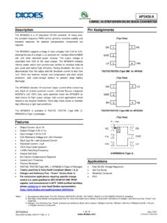
8 See characterization graphs for typical input to output operating voltage range and UVLOSTART and UVLOSTOP :For VIN<VOUT, VOUT will not remain in :VBOOST supply is derived from VOUT. 2011-2015 Microchip Technology 5 MCP16301 PERFORMANCE CURVESNote: Unless otherwise indicated, VIN=EN=12V, COUT=CIN=2X10 F, L=15 H, VOUT= , ILOAD=200mA,TA=+25 2-1 VOUT Efficiency vs. 2-2 VOUT Efficiency vs. 2-3 VOUT Efficiency vs. 2-4:12V VOUT Efficiency vs. 2-5:15V VOUT Efficiency vs. 2-6:Maximum Output current vs. VIN. Note:The graphs and tables provided following this note are a statistical summary based on a limited number ofsamples and are provided for informational purposes only. The performance characteristics listed hereinare not tested or guaranteed.
9 In some graphs or tables, the data presented may be outside the specifiedoperating range ( , outside specified power supply range) and therefore outside the warranted (%)IOUT (mA)VIN=30 VVIN=12 VVIN= 6 VVOUT= (%)IOUT (mA)VIN= 30 VVIN= 12 VVIN= 6 VVOUT= (%)IOUT(mA)VIN= 30 VVIN= 12 VVIN= 6 VVOUT= (%)IOUT(mA)VIN= 30 VVIN= 24 VVIN= 16 VVOUT= (%)IOUT(mA)VIN= 30 VVIN= 24 VVIN= 16 VVOUT= 1218243036 IOUT (mA) VIN (V) VOUT = VOUT = 5V VOUT = 12V MCP16301/HDS20005004D-page 6 2011-2015 Microchip Technology : Unless otherwise indicated, VIN=EN=12V, COUT=CIN=2X10 F, L=15 H, VOUT= , ILOAD=200mA,TA=+25 2-7:Input Quiescent current vs. 2-8:Switching Frequency vs. Temperature; VOUT= 2-9:Maximum Duty Cycle vs. Ambient Temperature; VOUT= 2-10:Peak current Limit vs.
10 Temperature; VOUT= 2-11: switch RDSON vs. 2-12:VFB vs. Temperature; VOUT= -25 -10520 35 50 65 80 95 110125IQ(mA)Ambient Temperature ( C)VOUT= 0 mAVIN= 12 VVIN= 6 VVIN= 30V455460465470475480485490495500505-40- 20020406080100 120 Switching Frequency (kHz)Ambient Temperature ( C)VIN= 12 VVOUT= 200 -25 -10 520 35 50 65 80 95 110125 Maximum Duty Cycle (%)Ambient Temperature ( C)VIN= 5 VIOUT= 200 mA60080010001200140016001800-40 -25 -10 520 35 50 65 80 95 110125 Peak current Limit (mA)Ambient Temperature ( C)VIN= 12 VVIN= 30 VVIN= 6 VVOUT= (m:)Boost Voltage (V)TA= 25 CVDS= 100 120 VFBV oltage (V)Ambient Temperature ( C)VIN= 12 VVOUT= 100 mA 2011-2015 Microchip Technology 7 MCP16301/HNote.