Transcription of Quad Buck Regulator Integrated Power Solution Data Sheet ...
1 Quad Buck Regulator Integrated Power Solution Data Sheet ADP5054 Rev. G Document Feedback Information furnished by Analog Devices is believed to be accurate and reliable. However, no responsibility is assumed by Analog Devices for its use, nor for any infringements of patents or other rights of third parties that may result from its use. Specifications subject to change without notice. No license is granted by implication or otherwise under any patent or patent rights of Analog Devices. Trademarks and registered trademarks are the property of their respective owners. One Technology Way, Box 9106, Norwood, MA 02062-9106, : 2015 2019 Analog Devices, Inc.
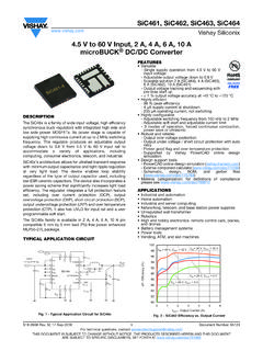
2 All rights reserved. Technical Support FEATURES Wide input voltage range: V to V output accuracy over full temperature range 250 kHz to 2 MHz adjustable switching frequency with individual frequency option Power regulation Channel 1 and Channel 2 Programmable 2 A/4 A/6 A sync buck regulators with low- side FET drivers Channel 3 and Channel 4: A sync buck regulators Flexible parallel operation Single 12 A output (Channel 1 and Channel 2 in parallel) Single 5 A output (Channel 3 and Channel 4 in parallel) Low 1/f noise density 40 V rms at VREF for 10 Hz to 100 kHz Precision enable with V accurate threshold Active output discharge switch FPWM/PSM mode selection Frequency synchronization input or output Power -good flag for Channel 1 output UVLO, OCP, and TSD protection 48-lead, 7 mm 7 mm LFCSP 40 C to +125 C operational junctional temperature range APPLICATIONS FPGA and processor applications Small cell base stations Security and surveillance Medical applications TYPICAL APPLICATION CIRCUIT OSCILLATORINTERNALVREG100mAQ1Q2L1L2 TO PADC0 VDDSELECTIVECFG34 CFG12(SS, 1/2 fSW,PARALLEL)(SS, 1/2 fSW,PARALLEL,SCLKSET)
3 C8 COMP1EN1 VREGVREGCHANNEL 1 BUCK(2A/4A/6A)CHANNEL 2 BUCK(2A/4A/6A)CHANNEL 3 BUCK( )CHANNEL 4 BUCK( )12617-001 Figure 1. GENERAL DESCRIPTION The ADP5054 combines four high performance buck regulators in a 48-lead LFCSP package that meets demanding performance and board space requirements. The device enables direct connection to high input voltages of up to V with no preregulators. Channel 1 and Channel 2 integrate high - side Power metal-oxide semiconductor field effect transistors (MOSFETs ) and low- side MOSFET drivers. External NFETs can be used in low- side Power devices to achieve an efficiency optimized Solution and to deliver a programmable output current of 2 A, 4 A, or 6 A.
4 Combining Channel 1 and Channel 2 in a parallel configuration provides a single output with up to 12 A of current . Channel 3 and Channel 4 integrate both high - side and low- side MOSFETs to deliver an output current of A. Combining Channel 3 and Channel 4 in a parallel configuration can provide a single output with up to 5 A of current . The switching frequency of the ADP5054 can be programmed or synchronized to an external clock from 250 kHz to 2 MHz, and an individual frequency configuration is available for each channel. The ADP5054 contains an individual precision enable pin on each channel for easy Power -up sequencing. The internal low 1/f noise reference is implemented in the ADP5054 for noise sensitive applications.
5 Table 1. Related Products Model Channels I2C Package ADP5050 Four bucks, one LDO Yes 48-Lead LFCSP ADP5051 Four bucks, supervisory Yes 48-Lead LFCSP ADP5052 Four bucks, one LDO No 48-Lead LFCSP ADP5053 Four bucks, supervisory No 48-Lead LFCSP ADP5054 Four high current bucks No 48-Lead LFCSP ADP5054 Data Sheet Rev. G | Page 2 of 31 TABLE OF CONTENTS Features .. 1 Applications .. 1 Typical Application Circuit .. 1 General Description .. 1 Revision History .. 3 Detailed Functional Block Diagram .. 4 Specifications .. 5 Buck Regulator Specifications .. 6 Absolute Maximum Ratings.
6 8 Thermal Resistance .. 8 ESD Caution .. 8 Pin Configuration and Function Descriptions .. 9 Typical Performance Characteristics .. 11 Theory of Operation .. 15 Buck Regulator Operational Modes .. 15 adjustable and Fixed Output Voltage .. 15 Internal Regulators (VREG and VDD) .. 15 Separate Supply Applications .. 16 Low- side Device Selection .. 16 Bootstrap Circuitry .. 16 Active Output Discharge Switch .. 16 Precision Enabling .. 16 Oscillator .. 16 Synchronization Input/Output .. 17 Soft Start .. 18 Parallel 18 Startup with Precharged Output .. 19 current -Limit Protection .. 19 Frequency Foldback .. 19 Pulse Skip in Maximum Duty.
7 19 Short-Circuit Protection (SCP) .. 20 Latch-Off Protection .. 20 Undervoltage Lockout (UVLO) .. 20 Power -Good Function .. 20 Thermal Shutdown .. 20 Applications Information .. 21 ADIsimPower Design Tool .. 21 Programming the Output Voltage .. 21 Voltage Conversion Limitations .. 21 current -Limit Setting .. 21 Soft Start Setting .. 22 Inductor Selection .. 22 Output Capacitor Selection .. 22 Input Capacitor Selection .. 23 Low- side Power Device Selection .. 23 Programming the UVLO Input .. 23 Compensation Components Design .. 24 Power 24 Junction Temperature .. 25 Design Examples .. 26 Setting the Switching Frequency .. 26 Setting the Output Voltage.
8 26 Setting the current Limit .. 26 Selecting the Inductor .. 26 Selecting the Output Capacitor .. 27 Selecting the Low- side MOSFET .. 27 Designing the Compensation Network .. 27 Selecting the Soft Start 27 Selecting the Input Capacitor .. 27 Printed Circuit Board Layout Recommendations .. 28 Typical Application Circuit .. 29 Factory Default Options .. 30 Outline Dimensions .. 31 Ordering Guide .. 31 Data Sheet ADP5054 Rev. G | Page 3 of 31 REVISION HISTORY 8/2019 Rev. F to Rev. G Change to Table 6 .. 10 Change to Figure 19 Caption .. 13 Changes to Low- side Power Device Selection Section and Table 12 .. 23 Changes to Printed Circuit Board Layout Recommendations Section and Figure 43.
9 28 Changes to Figure 44 .. 29 3/2019 Rev. E to Rev. F Changed Hiccup Detection to Hiccup Protection .. Throughout Changes to Table 14 .. 30 6/2018 Rev. D to Rev. E Changes to Forced PWM and Automatic PWM/PSM Modes Section .. 15 Change to Figure 44 .. 29 10/2017 Rev. C to Rev. D Changes to Figure 1 .. 1 Changes to Precision Enabling Section .. 15 Changes to Figure 44 .. 29 Updated Outline Dimensions .. 30 Changes to Ordering Guide .. 30 11/2016 Rev. B to Rev. C Changes to Figure 1 .. 1 Changes to Figure 29 .. 15 Deleted Factory Programmable Options Section and Table 14 to Table 18; Renumbered Sequentially .. 29 Changes to Factory Default Options Section.
10 29 Added Endnote 1, Table 14 .. 29 9/2015 Rev. A to Rev. B Changes to Figure 1 and Table 1 .. 1 Changes to Figure 2 .. 3 Changes to Table 3 .. 5 Changes to Figure 44 .. 28 4/2015 Rev. 0 to Rev. A Changes to Figure 3 .. 8 3/2015 Revision 0: Initial Version ADP5054 Data Sheet Rev. G | Page 4 of 31 DETAILED FUNCTIONAL BLOCK DIAGRAM + Q1 UVLO1 PVIN1SW1 BST1DL1 VREGVREGDRIVERDRIVERPGNDCONTROL LOGICAND MOSFETDRIVER HICCUP + + current LIMITSELECTIONFREQFOLDBACK+ + CHANNEL 1 BUCKDUPLICATECHANNEL 1 CHANNEL 2 BUCKCURRENT BALANCEEN2 COMP2FB2DL2 PVIN2SW2 BST2 DISCHARGESWITCHVID1EA1 CMP1 RTOSCILLATORSYNC/MODEFUNCTIONDECODERCFG1 2 CFG34 VDDVREGINTERNALREGULATORPVIN1 VREGPOWER-ONRESETPWRGDHOUSE-KEEPINGLOGIC ACS1 DISCHARGESWITCH+ Q3Q4 UVLO3 PVIN3SW3 BST3 VREGVREGDRIVERDRIVERPGND3 CONTROL LOGICAND MOSFETDRIVER HICCUP + + FREQFOLDBACK+ + CHANNEL 3 BUCKDUPLICATECHANNEL 3 CHANNEL 4 BUCKCURRENT BALANCEEN4 COMP4FB4