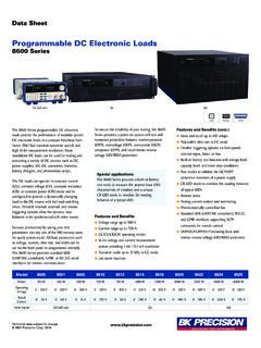
Transcription of MDL Series Programmable DC Electronic Load
1 MDL Series Programmable DC Electronic load Models: MDL001, MDL002, MDL200, MDL252, MDL305, MDL400, MDL505, MDL600 PROGRAMMING MANUAL Safety Summary The following general safety precautions must be observed during all phases of operation of this instrument. Failure to comply with these precautions or with specific warnings elsewhere in this manual violates safety standards of design, manufacture, and intended use of the instrument. We assume no liability for the customer s failure to comply with these requirements. ENVIRONMENTAL CONDITIONS This instrument is intended for indoor use, pollution degree 2 environments. It is designed to operate at a maximum relative humidity of 95% and at altitudes of up to 2000 meters. Refer to the specifications tables for the AC mains voltage requirements and ambient operating temperature range. BEFORE APPLYING POWER Verify that all safety precautions are taken.
2 Note the instrument's external markings described under "Safety Symbols". GROUND THE INSTRUMENT This product is a Safety Class 1 instrument (provided with a protective earth terminal). To minimize shock hazard, the instrument chassis and cover must be connected to an electrical ground. The instrument must be connected to the AC mains power through a grounded power cable, with the ground wire firmly connected to an electrical ground (safety ground) at the power outlet. Note: Any interruption of the protective (grounding) conductor or disconnection of the protective earth terminal will cause a potential shock hazard that could result in personal injury. DO NOT OPERATE IN AN EXPLOSIVE ATMOSPHERE Do not operate the instrument in the presence of fumes or flammable gases. KEEP AWAY FROM LIVE CIRCUITS Operating personnel must not remove instrument covers except as instructed in this guide for installing or removing Electronic load modules.
3 Component replacement and internal adjustments must be made only by qualified service personnel. Do not replace components with power cable connected. Under certain conditions dangerous voltages may exist even with the power cable removed. To avoid injuries, always disconnect power, discharge circuits, and remove external voltage sources before touching components. DO NOT SERVICE OR ADJUST ALONE Do not try to do some internal service or adjustment unless another person capable of rendering first aid resuscitation is present. Safety Symbols Direct current Alternating current Both direct and alternating current Protective earth (ground) terminal Attention (refer to accompanying documents) WARNING The WARNING sign denotes a hazard. It calls attention to a procedure, practice, or the like, which, if not correctly performed or adhered to, could result in personal injury.
4 Do not proceed beyond a WARNING sign until the indicated conditions are fully understood and met. CAUTION The CAUTION sign denotes a hazard. It calls attention to an operating procedure, or the like, which, if not correctly performed or adhered to, could result in damage to or destruction of part or all of the product. Do not proceed beyond a CAUTION sign until the indicated conditions are fully understood and met. Compliance Statements Disposal of Old Electrical & Electronic Equipment (Applicable in the European Union and other European countries with separate collection systems) This product is subject to Directive 2002/96/EC of the European Parliament and the Council of the European Union on waste electrical and Electronic equipment (WEEE), and in jurisdictions adopting that Directive, is marked as being put on the market after August 13, 2005, and should not be disposed of as unsorted municipal waste.
5 Please utilize your local WEEE collection facilities in the disposition of this product and otherwise observe all applicable requirements. CE Declaration of Conformity The DC Electronic load meets the requirements of Low Voltage Directive 73/23/EEC and Electromagnetic Compatibility Directive 89/336/EEC amended by 93/68/EEC. Low Voltage Directive - EN61010-1: 2001 EMC Directive - EN50081-1 - EN50082-1 Table of Contents Safety Summary .. 2 Compliance 4 Chapter 1 .. 6 Introduction to Programming .. 6 GPIB Capabilities of the Electronic load .. 6 RS-232 Capabilities of the Electronic load .. 7 USB-TMC Capabilities of the Electronic load .. 9 Programming the Status Registers .. 10 Chapter 2 .. 18 Introduction to SCPI .. 18 Types of SCPI Commands .. 18 Types of SCPI Messages .. 21 SCPI Data Formats .. 23 SCPI Command 25 Chapter 3 .. 27 SCPI Commands .. 27 Language Dictionary.
6 27 Common Commands .. 28 Subsystem Commands .. 35 Channel Commands .. 36 Trigger Commands .. 37 System 38 Trace Commands .. 45 Source Commands .. 48 List Commands .. 68 Measurement 71 Program 74 Other Commands .. 79 SCPI Command Tree .. 80 Chapter 4 .. 88 Programming Examples .. 88 Introduction .. 88 Programming the Input .. 89 Programming Lists .. 92 Chapter 5 .. 93 Error Messages .. 93 6 Chapter 1 Introduction to Programming This guide contains programming information for the B&K Precision MDL Series DC Electronic load . Models in this Series include the MDL001, MDL002, MDL200, MDL252, MDL305, MDL400, MDL505, and MDL600. Unless otherwise noted, this document will refer to all of these instruments as Electronic load . GPIB Capabilities of the Electronic load All Electronic load functions except for setting the communication parameters are Programmable over the GPIB.
7 The IEEE capabilities of the Electronic load are described in the table below. GPIB Capabilities Response Interface Function Talker/Listener All Electronic load functions except for setting the communication parameters are Programmable over the GPIB. The Electronic load can send and receive messages over the GPIB. Status information is sent using a serial poll. AH1, SH1, T6, L4 Service Request The Electronic load sets the SRQ line true if there is an enabled service request condition. SR1 Remote/Local In local mode, the Electronic load is controlled from the front panel but will also execute commands sent over the GPIB. The Electronic load powers up in local mode and remains in local mode until it receives a command over the GPIB. Once the Electronic load is in remote mode, the front panel REM annunciator turns on, all front panel keys (except Shift + Local) are disabled, and the display is in normal metering mode.
8 Pressing Shift + Local on the front panel returns the Electronic load to local mode. This can be disabled using local lockout so that only the controller or the power switch can return the Electronic load to local mode. RL1 Device Trigger The Electronic load will respond to the device trigger function. DT1 Group Execute Trigger The Electronic load will respond to the group execute trigger function. GET 7 Device Clear The Electronic load responds to the Device Clear (DCL) and Selected Device Clear (SDC) interface commands. They cause the Electronic load to clear any activity that would prevent it from receiving and executing a new command (including *WAI and *OPC?). DCL and SDC do not change any programmed settings. DCL,SDC GPIB Address The Electronic load operates from a GPIB address that is set from the front panel. To set the GPIB address, press Shift + (System menu) on the front panel and enter the address using the Entry keys.
9 The address can be set from 0 to 30. The GPIB address is stored in non-volatile memory. RS-232 Capabilities of the Electronic load Use a cable with two serial interfaces (DB9) to connect the Electronic load and PC. It can be activated by selecting <RS-232> in <Communication> of the System menu (Shift + on the front panel). NOTE: There are two serial interfaces on the rear panel of the MDL001: the left 9-pin COM interface is the RS-232 communication interface and the right 9-pin COM serial port connection is not for use. All SCPI commands are available through RS-232 programming. The EIA RS-232 standard defines the interconnections between data terminal equipment (DTE) and data communications equipment (DCE). The Electronic load is designed to be a DTE and can be connected to another DTE such as a PC COM port through a null modem cable. NOTE: The RS-232 settings in your program must match the settings specified in the front panel System menu.
10 Press Shift + on the front panel to enter the System menu if you need to change the settings. You can break data transmissions by sending a ^C or ^X character string to the Electronic load . This clears any pending operation and discards any pending output. RS-232 Data Format The RS-232 data is a 10-bit word with one start bit and one stop bit. The number of start and stop bits are not Programmable . However, the following parameters are selectable in the System menu using the front panel Shift + key. Parity=None Start Bit 8 Data Bits Stop Bit 8 Baud Rate The System menu (Shift + ) lets you select one of the following baud rates, which are stored in non-volatile memory: 4800, 9600, 19200, 38400, 57600, or 115200. Parity None - eight data bits without parity Even - seven data bits with even parity Odd - seven data bits with odd parity RS-232 Flow Control The RS-232 interface supports the following flow control options.