Transcription of Mitigation technique of the SiC MOSFET gate voltage ...
1 IntroductionThe gate drive requirements of Silicon-Carbide (SiC) MOSFETs are similar to Silicon MOSFETs and IGBTs; however thesuperior switching capability combined with the specific electrical characteristics of these power devices and parasitic elementsrequires special attention on the gate drive circuit and layout design to avoid the ringing and overshoot phenomena frombecoming an issue. In particular, induced Miller turn-on effects and amplitude voltage glitches across the gate-source terminalsmay be slightly exacerbated due to the higher target commutation speed and because the negative gate voltage amplitudemaximum rating (AMR) is different from the positive one contrary to what is typically expected in silicon devices. It is thereforevery important to establish proper driving conditions by preventing these anomalies with appropriate Mitigation methods, withoutoverly compromising the device s switching performance.
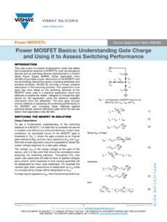
2 The use of a Miller clamp instead of standard gate driverconfigurations allows optimal clamping and the best possible gate control under high-speed switching events, to completelyeliminate unwanted Miller induced turn-on effects. In order to demonstrate this concept, the 2nd generation 650 V SiC MOSFET sfrom the STPOWER family in an HiP247 package are employed to investigate these anomalies arising at the gate-sourceterminals during the switching transients. Mitigation technique of the SiC MOSFET gate voltage glitches with Miller clamp AN5355 Application noteAN5355 - Rev 1 - July 2019 - By Anselmo Liberti, Giuseppe Catalisano, Luigi AbbatelliFor further information contact your local STMicroelectronics sales turn-on and glitch phenomena generationIn bridge topologies, during the high negative slew rate of VDS voltage of one switch, a current is injected towardsthe gate by the Miller capacitance of the complementary switch (CGD).
3 A voltage spike appears on the switch gatedue to the drop caused by the Miller current across the overall gate path impedance. If the positive VGS spikeexceeds the switch VGS(th) during the rapid rise of the VDS transient , a shoot through may occur across the halfbridge. Power devices with low threshold voltage such as SiC MOSFETs are more likely to suffer from inducedturn-on, which is why certain precautions are required. The negative temperature coefficient of the thresholdvoltage can also foster this phenomenon and potential risks of capacitive parasitic turn-on can be obviated byreducing the RGoff 1. Miller turn-on phenomenon due to fast rising VDS transient in half bridge topologyHV_BUSGND_ POWERPHASERG-ONRG-OFFRG_ONRG_OFFRG_INCGD CGSCDSVH_HSGND_HSRDRIVRDRIVDRIVERVgs_spi keVH_LSGND_LSThis switch isturning ONgenerating the halfbridge s dv/dtThis switch is OFFLoad current direction(High side hard- switching turn-on)RG_INCGDCGSCDSIn general, the duality of glitch phenomena is generated due to the applied positive or negative dv/dt on theswitching node resulting in an instantaneous current IGD flow through the charge of the MOSFET Millercapacitance CGD.
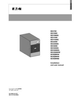
4 Some current through CGD flows out of the gate terminal and back through the drive sinkresistance, which produces a spurious voltage spike at the MOSFET . During the negative dv/dt, occurring at turn-off of the complementary switch in half bridge topology, the negative VGS peak has to be kept within the AMR toavoid any possible gate oxide turn-on and glitch phenomena AN5355 - Rev 1page 2/19 Figure 2. Miller current generation with positivedv/dtFigure 3. Miller current generation with negativedv/dtFigure 4. Duality of glitch phenomenaLow sideHigh sideTDT= Dead TimeVDS_HSVGS_LSID_HSRisk of parasitic turn-onVGS_pk+Risk of generating peak below AMRVGS_pk Positive dv/dt for LSNegative dv/dt for LSHSLSI nductive parasitic turn-on can be also generated during turning off of the load current when a voltage is inducedacross the emitter stray inductance.
5 In this condition, the decay of the current induces a voltage on source strayinductance that shifts the source potential to the negative level. The inductive parasitic turn-on, however, can belimited by increasing the RGoff value. Useful approaches that help control glitch phenomena include limiting dV/dtrating, minimizing the parasitic gate loop inductance, selecting a driver with low pull down output impedance orimplementing negative gate bias. False turn-on phenomenon due to a fast positive dv/dt rating can be also limitedby using a separate turn-off gate driving network path or putting a small capacitor between the gate to source atthe expense of reducing the efficiency improvement with higher switching losses. More advanced techniques,such as "Active Miller Clamp", can be used to provide a low impedance path without compromising the turn-offslew rate Glitch phenomena generation AN5355 - Rev 1page 3 techniques for induced G-S glitchesDriving the switch gate to a negative voltage increases the safety margin between the spike level and the VGS(th)threshold.
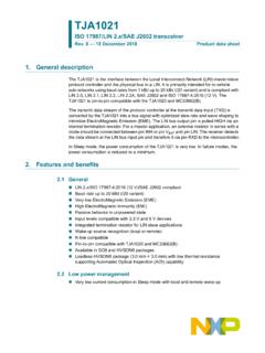
6 However, a negative voltage that is too low increases the risk of exceeding the lower AMR limit of VGSdue to the negative spikes caused by CGD discharge in the opposite dv/dt transient ; the best trade-off is usually anegative voltage between -2 V and -5 V in according to the maximum rating of the involved device. The use of anactive Miller clamp to mitigate induced G-S glitches allows to establish a low impedance path withoutcompromising the turn-off slew rate control when the external switch is already off, which helps avoid the inducedturn-on phenomenon. Moreover, it also enables the turn-off gate resistor on the basis of turn-off speedrequirements only (EOFF), and helps reduce the negative gate spike caused by CGD discharge during the oppositedv/dt 5. Negative gate driving+VL_LSVH_LSRG_ONRG_OFFRDRIVDRIVER GND_ POWERPHASERG_INCGDCGSCDSVgs_spikeIVLF igure 6.
7 Active Miller CLAMPV-V+ active Miller clamp worksThe additional switch between the gate and source controls the Miller current during a high dV/dt situation andkeeps the SiC MOSFET totally off by shorting the gate-to-source path after a voltage level is reached. Duringturn-off switching , the gate voltage is detected and the clamp is activated when the gate voltage drops below athreshold voltage value relative to VEE (see Figure 6. Active Miller CLAMP). The currents across the Millercapacitance are shunted by the transistor instead of flowing through the output driver VOUT. The Miller clampfunction is only effective during SiC MOSFET turn-off and does not affect SiC turn-on. It provides cost savingsolution by eliminating the need for a negative supply voltage and additional capacitors that reduce techniques for induced G-S glitches AN5355 - Rev 1page 4/19 Figure 7.
8 Active Miller clamp technology+12VV-V++12V+12VG-ONVL_LSEEV-V + coupling through (Miller) capacitanceAnother important parameter to be taken in account beside the Miller transfer capacitance in order to minimize thesensitivity to the ringing phenomena is the Crss Ciss ratio in terms of maximum amplitude at VDS = 0 V and how itstrend decreases over the VDS variation. When a voltage appears across the drain and source of the MOSFET , itcouples to the gate and causes the internal gate source capacitor to charge. If the voltage on the gate increasesbeyond the MOSFETs threshold voltage , it starts to turn back on which can cause cross conduction. The ratio ofthe capacitances Crss and Ciss determines the severity of this SiC MOSFETs also improves on the 1st generation (Gen1) with better CGD/CGS ratio, which determinesvoltage coupling, and a smaller CGD with bigger CGS minimizes the residual VGS when device is off (capacitivedivider).
9 Figure 8. SiC MOSFET intrinsic capacitancesAN5355 voltage coupling through (Miller) capacitance AN5355 - Rev 1page 5/19 Figure 9. Capacitive ratio CGD/CGS Gen1 vs. Gen2 SiC MOSFETsAs visible from the capacitive ratio between Gen1 SiC MOSFET SCT20N120 and Gen2 SiC MOSFETSCTH90N65G2V-7 of the above attached datasheet capacitance variation curves, the reverse transfercapacitance Crss is 11 (Gen1) vs 20 (Gen2) times smaller than the input capacitance Ciss at 10 V and 28 (Gen1)vs 55 (Gen2) at 100 coupling through (Miller) capacitance AN5355 - Rev 1page 6/192 voltage glitch suppression with active Miller clampThe Miller clamp function implemented on the new ST gapLITE driver has been tested for the reduction of bothpositive and negative glitches: positive glitches could cause thermal stresses on the device due to spurious turn-on effects, while negative glitches could jeopardize the reliability of the gate oxide.
10 The Miller effect has beendeeply investigated using two SiC MOSFETs connected in a DC/AC half-bridge configuration at Tamb 25 C anddriven by gapLITE. The SCTW35N65G2V 2nd generation 650 V / 45 A planar SiC MOSFET by ST in an HiP247package has been used as the test vehicle. The tested device features extremely low gate charge and inputcapacitances, very fast and robust intrinsic body diode capacitance, very high operating temperature capability(TJ = 200 C), and very small RDS(on) variation over bridge inverter and setupThe tests and measurements were performed on a half-bridge inverter topology board implemented on a PCB, asshown 10. Half bridge inverter topologyVIN= 400 VDCFILTERVout=110 VACSTGAP2SS-PWMSTGAP2SS-PWMHalf Bridge InverterFigure 11. Half bridge inverter prototypeDUT(SCTW35N65G2V)UpperdeviceLow erdeviceIsolated supplyfor -5V/+18 VDetails of the driver:closed to the DUTFILTERGate Driver Board650V Gen2 SiC MOSFETsAN5355 voltage glitch suppression with active Miller clampAN5355 - Rev 1page 7/19 Figure 12.