Transcription of Module 4: DC-DC Converters
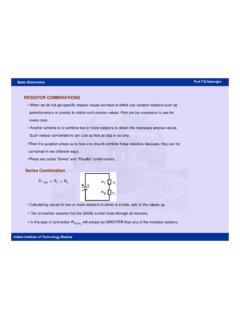
1 NPTEL Electrical Engineering Introduction to Hybrid and Electric Vehicles Joint initiative of IITs and IISc Funded by MHRD Page 1 of 55 Module 4: DC-DC Converters Lec 9: DC-DC Converters for EV and HEV Applications DC-DC Converters for EV and HEV Applications Introduction The topics covered in this chapter are as follows: EV and HEV configuration based on power Converters Classification of Converters Principle of Step Down Operation Buck converter with RLE Load Buck converter with RL Load and Filter Electric Vehicle (EV) and Hybrid Electric Vehicle (HEV) Configurations In Figure 1 the general configuration of the EV and HEV is shown. Upon examination of the general configurations it can be seen that there are two major power electronic units DC-DC converter DC-AC inverter Figure 1:General Configuration of a Electric Vehicle [1] NPTEL Electrical Engineering Introduction to Hybrid and Electric Vehicles Joint initiative of IITs and IISc Funded by MHRD Page 2 of 55 Usually AC motors are used in HEVs or EVs for traction and they are fed by inverter and this inverter is fed by DC-DC converter (Figure 1).
2 The most commonly DC-DC Converters used in an HEV or an EV are: Unidirectional Converters : They cater to various onboard loads such as sensors, controls, entertainment, utility and safety equipments. Bidirectional Converters : They are used in places where battery charging and regenerative braking is required. The power flow in a bi-directional converter is usually from a low voltage end such as battery or a supercapacitor to a high voltage side and is referred to as boost operation. During regenerative braking, the power flows back to the low voltage bus to recharge the batteries know as buck mode operation. Both the unidirectional and bi-directional DC-DC Converters are preferred to be isolated to provide safety for the lading devices. In this view, most of the DC-DC Converters incorporate a high frequency transformer.
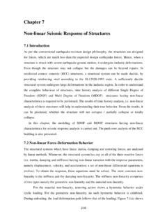
3 Classification of Converters The converter topologies are classified as: Buck converter : In Figure 2a a buck converter is shown. The buck converter is step down converter and produces a lower average output voltage than the dc input voltage . boost converter : In Figure 2b a boost converter is shown. The output voltage is always greater than the input voltage . Buck- boost converter : In Figure 2c a buck- boost converter is shown. The output voltage can be either higher or lower than the input voltage . NPTEL Electrical Engineering Introduction to Hybrid and Electric Vehicles Joint initiative of IITs and IISc Funded by MHRD Page 3 of 55 Figure 2a: General Configuration Buck converter Figure 2b: General Configuration boost converter Figure 2c: General Configuration Buck- boost converter 1S1 DRLEinV1iinVLe1S1D0 VCLLi0iRNPTEL Electrical Engineering Introduction to Hybrid and Electric Vehicles Joint initiative of IITs and IISc Funded by MHRD Page 4 of 55 Principle of Step Down Operation The principle of step down operation of DC-DC converter is explained using the circuit shown in Figure 3a.
4 When the switch 1 Sis closed for time duration1T, the input voltage inVappears across the load. For the time duration 2T is switch 1 Sremains open and the voltage across the load is zero. The waveforms of the output voltage across the load are shown in Figure 3b. Figure 3a: Step down operation Figure 3b: voltage across the load resistance The average output voltage is given by 11101 ToavgoutinininTVv dtVfTVDVTT (1) The average load current is given by oavginoavgVDVIRR (2) Where T is the chopping period 1 TDT is the duty cycle f is the chopping frequency The rms value of the output voltage is given by 1/ 2201 DTormsoutinVv dtDVT (3)
5 1 SinVoutvR+-+-outvinVinV1T2TT1 TtNPTEL Electrical Engineering Introduction to Hybrid and Electric Vehicles Joint initiative of IITs and IISc Funded by MHRD Page 5 of 55 In case the converter is assumed to be lossless, the input power to the converter will be equal to the output power. Hence, the input power (inP) is given by 220011 DTDT outininout outvVPv i dtdtDTTRR (4) The effective resistance seen by the source is (using equation 2) ineffoavgVRRID (5) The duty cycle D can be varied from 0 to 1 by varying1T, Torf. Thus, the output voltage oavgVcan be varied from 0 to inVby controlling Dand eventually the power flow can be controlled.
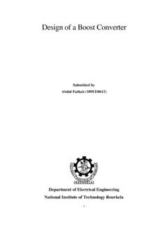
6 The Buck converter with RLE Load The buck converter is a voltage step down and current step up converter . The two modes in steady state operations are: Mode 1 Operation In this mode the switch 1S is turned on and the diode 1D is reversed biased, the current flows through the load. The time domain circuit is shown in Figure. The load current, in sdomain, for mode 1 can be found from 1101( )( )inVERi ssLi sLIss (6) Where 01 Iis the initial value of the current and 011II . Figure 4: Time domain circuit of buck converter in mode 1 Figure 5: Time domain circuit of buck converter in mode 2 RLEinV1iRLE1iNPTEL Electrical Engineering Introduction to Hybrid and Electric Vehicles Joint initiative of IITs and IISc Funded by MHRD Page 6 of 55 From equation 6, the current 1()isis given by 11()()inVELIiss R sLR sL (7) In time domain the solution of equation 7 is given by //11( )1tR LtR LinVEi tI eeR (8) The mode1 is valid for the time duration100t TtDT.
7 At the end of this mode, the load current becomes 112()i t TDTI (9) Mode 2 Operation In this mode the switch 1 Sis turned off and the diode 1 Dis forward biased. The time domain circuit is shown in Figure 5. The load current, in sdomain, can be found from 2202( )( )ERi ssLi sLIs (10) Where 02I is the initial value of load current. The current at the end of mode1 is equal to the current at the beginning of mode 2. Hence, from equation 9 02 Iis obtained as 022II (11) Hence, the load current is time domain is obtained from equation 10 as //22( )1tR LtR LEi tI eeR (12) Determination of 1I and2I At the end of mode 2 the load current becomes 223((1) )i t TD TI (13) At the end of mode 2, the converter enters mode 1 again.
8 Hence, the initial value of current in mode 1 is 0131 III (14) From equation 8 and equation 12 the following relation between 1I and 2I is obtained as //211 DTR LDTR LinVEII eeR (15) (1)/(1)/3121D TR LD TR LEIII eeR (16) NPTEL Electrical Engineering Introduction to Hybrid and Electric Vehicles Joint initiative of IITs and IISc Funded by MHRD Page 7 of 55 Solving equation 15 and equation 16 for 1 Iand 2 Igives 111 DainDVeEIReR (17) 211 DainDVeEIReR (18) Where TRRaLfL (19) where fis the chopping frequency.
9 Current Ripple The peak to peak current ripple is given by (1)(1)211111 DaaD aDaaD aininaaVVeeeeeeIIIRefLae (20a) In casefLR ,0a . Hence, for the limit 0a equation 20 becomes (1)inV DDIfL (20b) To determine the maximum current ripple (maxI ), the equation 20a is differentiated D. The value of maxI is given by maxtanh4inVRIRfL (21) For the condition4fLR , tanh44 RRfLfL (22) Hence, the maximum current ripple is given by max4inVIfL (23) If equation 20b is used to determine the maximum current ripple, the same result is obtained.
10 NPTEL Electrical Engineering Introduction to Hybrid and Electric Vehicles Joint initiative of IITs and IISc Funded by MHRD Page 8 of 55 Continuous and Discontinuous Conduction Modes In case of large off time, particularly at low switching frequencies, the load current may be discontinuous, 22((1) )i t TD T will be zero. The necessary condition to ensure continuous conduction is given by 1100111 DainDDaDinVeEIReREeVe (24) The Buck converter with R Load and Filter The output voltage and current of the converter contain harmonics due to the switching action. In order to remove the harmonics LC filters are used. The circuit diagram of the buck converter with LC filter is shown in Figure 6.