Transcription of Motor Control Sensor Feedback Circuits
1 M AN894. Motor Control Sensor Feedback Circuits A list of the sensors that can be used to Feedback Author: Jim Lepkowski information to a microcontroller are listed below: Microchip Technology Inc. Current sensors - Shunt resistor INTRODUCTION. - Current-sensing transformer Sensors are a critical component in a Motor Control - Hall effect current Sensor system. They are used to sense the current, position, Speed/position sensors speed and direction of the rotating Motor . Recent - Quadrature encoder advancements in Sensor technology have improved the accuracy and reliability of sensors, while reducing - Hall efect tachometer the cost. Many sensors are now available that integrate Back EMF/Sensorless Control method the Sensor and signal-conditioning circuitry into a single package. In most Motor Control systems, several sensors are used to provide Feedback information on the Motor .
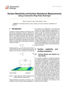
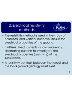
2 These sensors are used in the Control loop and to improve the reliability by detecting fault conditions that may damage the Motor . As an example, Figure 1 pro- vides a block diagram of a DC Motor Control system to show the Sensor Feedback provided for a typical Motor Control . Power Management Torque PICmicro . Speed Input Microcontroller Driver Motor Direction Current Sensor Feedback Sensors * Speed * Shaft Position * Rotation Direction FIGURE 1: Typical DC Motor Block Diagram. 2003 Microchip Technology Inc. DS00894A-page 1. AN894. CURRENT SENSORS applications. A summary of the advantages and disadvantages of each of the current sensors is The three most popular current sensors in Motor provided in Table 1. Control applications are: Figure 2 shows an example of an AC Motor powered by Shunt resistors a three-phase inverter bridge circuit.
3 This example Hall effect sensors shows that the composite current of all three Insulated Current transformers Gate Bipolar Transistor (IGBT) circuit legs can be measured with a single shunt resistor, or that the Shunt resistors are popular current sensors because current in each individual leg can be determined with they provide an accurate measurement at a low cost. three shunt resistors. Figure 2 shows a system that Hall effect current sensors are widely used because uses shunt resistors. However, Hall effect and current- they provide a non-intrusive measurement and are sensing transformers can also be used to provide the available in a small IC package that combines the current measurement . Sensor and signal-conditioning circuit. Current-sensing transformers are also a popular Sensor technology, especially in high-current or AC line-monitoring TABLE 1: COMPARISON OF CURRENT SENSING METHODS.
4 Current Sensing Method Shunt Resistor Hall Effect Current Sensing Transformer Accuracy Good Good Medium Accuracy Good Poor Good Cost Low High Medium Isolation No Yes Yes High Current-Measuring Poor Good Good Capability DC Offset Problem Yes No No Saturation/Hysteresis No Yes Yes Problem Power Consumption High Low Low Intrusive measurement Yes No No AC/DC Measurements Both Both Only AC. Current measurement with Current measurement with a Single Shunt Resistor AC Three Shunt Resistors AC. Motor Motor VDC VDC. IA IB IC. IA IB IC VOUT_C. I = IA+ IB + IC VOUT_A VOUT_B. VOUT. RSENSE R SENSE_A. RSENSE_B RSENSE_C. FIGURE 2: AC Motor Current measurement . DS00894A-page 2 2003 Microchip Technology Inc. AN894. Shunt Resistors Special-purpose, low inductance resistors are required if the current has a high-frequency Shunt resistors are a popular current-sensing Sensor content.
5 Because of their low cost and good accuracy. The The power rating of RSENSE must be evaluated voltage drop across a known low value resistor is because the I2 x R power dissipation can produce monitored in order to determine the current flowing self heating and a change in the nominal through the load. If the resistor is small in magnitude, resistance of the shunt. the voltage drop will be small and the measurement will not have a major effect on the Motor circuit. The power Special-purpose, shunt current measurement resistors dissipation of the resistance makes current shunts are available from a number of vendors. If standard impractical for measurements of more than resistors are used, it is recommended that metal-film approximately 20 amperes. resistors be used rather than wire-wound resistors that have a relatively large inductance.
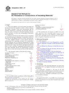
6 The selection criteria of a shunt current resistor requires the evaluation of several trade-offs, including: A shunt resistor can also be created from the trace resistance on a PCB, as shown in Figure 3. PCB shunt Increasing R SENSE increases the VSENSE voltage, resistors offer a low cost alternative to discrete resis- which makes the voltage offset (VOS) and input tors. However, their accuracy over a wide temperature bias current offset (IOS) amplifier errors less range is poor when compared to a discrete resistor. significant. The temperature coefficient of a copper PCB trace A large RSENSE value causes a voltage loss and a shunt resistor is equal to approximately + C. reduction in the power efficiency due to the I2 x R Further details on PCB trace resistors are given in ref- loss of the resistor. erence (2). A large RSENSE value will cause a voltage offset to the load in a low-side measurement that may impact the EMI characteristics and noise sensitivity of the system.
7 Trace resistance is based on: Example: What is the resistance of the PCB shunt resistor * Length (L) using the parameters listed below? * Thickness (t) Given: 1 oz Cu PCB. * Width (w) w = 50 mils ( in). * resistivity ( ) L = 1 inch I = 5 ampere * 1 oz. Copper (Cu) is defined to be a layer L / w = number of squares ( ). with 1 oz. of Cu per square foot. = 1 in / in = 20 squares t Copper R (L / w) x R. -inch (20 squares) x m /. 10 m . R ( m / ) x [(1 oz. Cu) / (# oz. Cu)]. P = I2 x R. = (5A)2 x ( ). = Watt RPCB.. L. t PCB Trace Resistor w FIGURE 3: PCB Shunt Resistor. 2003 Microchip Technology Inc. DS00894A-page 3. AN894. High-Side vs. Low-Side Current Shunt High-side resistive shunt measurements will not have a Measurements significant impact on the system if the sensing resistor is small and the resulting voltage drop across the shunt SYSTEM INTEGRATION ISSUES is small compared to the supply voltage.
8 In contrast, low-side monitoring disrupts the ground path of the Shunt resistors can provide either a high-side or low- load, which can cause noise and EMI problems in the side measurement of the current through the load, as system. shown in Figure 4. A high-side monitor has the resistor connected in series with the power source, while the Low-side current measurements are often chosen low-side monitor locates the resistor between the load because low voltage op amps can be used to sense the and the ground current return path. Both approaches voltage across the shunt resistor. Note that low-side pose a trade-off to the designer. The attributes of the monitoring is not possible in some applications two methods, along with the typical monitor Circuits , will because the ground connection is made via the be shown in the following sections.
9 Reference (3) mechanical mounting of the Motor on the chassis or provides more details on high-side and low-side metal frame. For systems powered via a single wire shunts. connection, it may not be practical to insert a shunt resistor between the device and the chassis that High-side current measurements are the preferred functions as the ground wire. method from a system-integration standpoint because they are less intrusive than low-side measurements. The trade-off with the high-side measurement is that the circuitry is more complex than the low-side method. RSENSE ILOAD. ILOAD. VSENSE Load VS + +. - Load VS - measurement VSENSE. measurement Circuit Circuit RSENSE. High-Side Current measurement Low-Side Current measurement ILOAD = VSENSE / RSENSE ILOAD = VSENSE / RSENSE. FIGURE 4: High-Side and Low-Side Resistive Current Shunts.
10 DS00894A-page 4 2003 Microchip Technology Inc. AN894. HIGH-SIDE CURRENT SHUNT Disadvantages: MEASUREMENTS The VSENSE voltage is approximately equal to the High-side current measurements can be implemented supply voltage, which may be beyond the with a differential amplifier circuit that produces an maximum input voltage range of the operational output voltage that is proportional to VSENSE or the amplifier. current flowing through the load. Figure 5 provides an A differential amplifier's CMRR will be degraded example of a high-side shunt circuit. The differential by mismatches in the amplifier resistors. amplifier circuit can be implemented with an op amp The input impedance of the differential circuit is and discrete resistors or with an integrated IC device. relatively low and is asymmetrical. The input Integrated differential amplifier ICs are available from a impedance at the amplifier's non-inverting input is number of semiconductor vendors and offer a equal to R IN + R*, while the impedance at the convenient solution because the amplifier and well- inverting terminal is equal to R IN.