Transcription of MT-055: Chopper Stabilized (Auto-Zero) Precision Op Amps
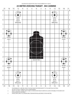
1 MT-055 TUTORIAL Chopper Stabilized (Auto-Zero) Precision Op Amps Chopper AMPLIFIERS For the lowest offset and drift performance, Chopper - Stabilized (auto-zero) amplifiers may be the only solution. The best bipolar amplifiers offer offset voltages of 25 V and V/ C drift. Offset voltages less than 5 V with practically no measurable offset drift are obtainable with choppers, albeit with some penalties. A basic Chopper amplifier circuit is shown in Figure 1 below. When the switches are in the "Z" (auto-zero) position, capacitors C2 and C3 are charged to the amplifier input and output offset voltage, respectively.
2 When the switches are in the "S" (sample) position, VIN is connected to VOUT through the path comprised of R1, R2, C2, the amplifier, C3, and R3. The chopping frequency is usually between a few hundred Hz and several kHz, and it should be noted that because this is a sampling system, the input frequency must be much less than one-half the chopping frequency in order to prevent errors due to aliasing. The R1-C1 combination serves as an antialiasing filter. It is also assumed that after a steady state condition is reached, there is only a minimal amount of charge transferred during the switching cycles.
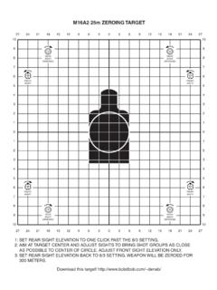
3 The output capacitor, C4, and the load, RL, must be chosen such that there is minimal VOUT droop during the auto-zero cycle. CHOPPERSWITCHDRIVERVINVOUTAMPC1C2C3C4 SZSZS = SAMPLEZ = AUTO-ZEROR1R2R3RL Figure 1: Classic Chopper Amplifier , 10/08, WK Page 1 of 6 MT-055 AUTO-ZERO Chopper Stabilized OP AMP The basic Chopper amplifier of Fig. 1 can pass only very low frequencies because of the input filtering required to prevent aliasing. In contrast to this, the Chopper - Stabilized architecture shown in Figure 2 is most often used in Chopper amplifier implementations.
4 _++_SZSZA1A2C1C2 NULLNULL IN+INVOUTS = SAMPLEZ = AUTO-ZERO Figure 2: Modern Auto-Zero ( Chopper - Stabilized ) Op Amp In this circuit, A1 is the main amplifier, and A2 is the nulling amplifier. In the sample mode (switches in "S" position), the nulling amplifier, A2, monitors the input offset voltage of A1 and drives its output to zero by applying a suitable correcting voltage at A1's null pin. Note, however, that A2 also has an input offset voltage, so it must correct its own error before attempting to null A1's offset.
5 This is achieved in the auto-zero mode (switches in "Z" position) by momentarily disconnecting A2 from A1, shorting its inputs together, and coupling its output to its own null pin. During the auto-zero mode, the correction voltage for A1 is momentarily held by C1. Similarly, C2 holds the correction voltage for A2 during the sample mode. In modern IC Chopper - Stabilized op amps, the storage capacitors C1 and C2 are on-chip. Note in this architecture that the input signal is always connected to the output, through A1.
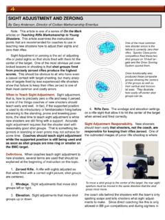
6 The bandwidth of A1 thus determines the overall signal bandwidth, and the input signal is not limited to less than one-half the chopping frequency as in the case of the traditional Chopper amplifier architecture. However, the switching action does produce small transients at the chopping frequency, that can mix with the input signal frequency and produce intermodulation distortion. A patented spread-spectrum technique is used in the AD8571/AD8572/AD8574 series of single-supply Chopper - Stabilized op amps, to virtually eliminate intermodulation effects.
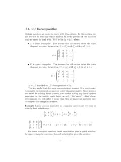
7 These devices use a pseudorandom chopping frequency swept between 2 kHz and 4 kHz. Figure 3 compares the intermodulation distortion of a traditional Chopper Stabilized op amp. Page 2 of 6 MT-055 The (AD8551/AD8552/AD8554, left) uses a fixed 4 kHz chopping frequency, and the AD8571/AD8572/AD8574 (right) uses the pseudorandom chopping frequency. AD8551/52/54 FIXED CHOPPING FREQUENCY:4kHzAD8571/72/74 PSEUDORANDOM CHOPPING FREQ: 2kHz - 4kHzINPUT SIGNAL = 1mV RMS, 200 HzOUTPUT SIGNAL: 1V RMS, 200 HzGAIN = 60dBVS= +5VG = 60dBVS= +5VG = 60dB Figure 3: Intermodulation Product: Fixed Versus Pseudorandom Chopping Frequency A comparison between fixed and pseudorandom chopping on the voltage noise is shown in Figure 4 below.
8 Notice for the fixed chopping frequency, there are distinct peaks in the noise spectrum at the odd harmonics of 4 kHz, whereas with pseudorandom chopping, the spectrum is much more uniform, although the average noise level is higher. AD8551/52/54 FIXED CHOPPING FREQUENCY:4kHzAD8571/72/74 PSEUDORANDOM CHOPPING FREQUENCY 2kHz - 4kHzVS= +5 VRS= 0 VS= +5 VRS= 0 Figure 4: Voltage Noise Spectral Density Comparison: Fixed Versus Pseudorandom Chopping Frequency Page 3 of 6 MT-055 Another method for reducing the intermodulation effects the switching action of auto-zero amplifiers is through a patented combination of auto- zeroing and chopping as used in the AD8628/AD8629/AD8630 family.
9 This unique topology allows these amplifiers to maintain their low offset voltage over a wide temperature range and over their operating lifetime. The AD8628/AD8629/AD8630 also optimize the noise and bandwidth over previous generations of auto-zero amplifiers, offering the lowest voltage noise of any auto-zero amplifier by more than 50%. Other designs use either auto- zeroing or chopping to add Precision to the specifications of an amplifier. Auto- zeroing results in low noise energy at the auto- zeroing frequency, at the expense of higher low frequency noise due to aliasing of wideband noise into the auto-zeroed frequency band.
10 Chopping results in lower low frequency noise at the expense of larger noise energy at the chopping frequency. The AD8628/AD8629/AD8630 family uses both auto- zeroing and chopping in a patented "ping-pong" arrangement to obtain lower low frequency noise together with lower energy at the chopping and auto- zeroing frequencies, maximizing the signal-to-noise ratio for the majority of applications without the need for additional filtering. The relatively high clock frequency of 15 kHz simplifies filter requirements for a wide, useful, noise-free bandwidth.