Transcription of New Mach3 tutorial - Stepper Motor, Stepper Motor Driver ...
1 1 Mach3 tutorial Setting up a basic three axis milling machine. Based on Mach3 Purpose. The purpose of this tutorial is to help and to guide the user to, step by step, set up and tune the Mach3 CNC controller application for use on a basic 3 axis milling machine. We will go thru the steps of setting up the emergency stop, the charge pump circuit the main axis motors, the spindle and coolant as well as the home switches and the software based over-travel limits. The tutorial is based on the Mach3 series and is meant to be used as complement to the existing Using Mach 3 Mill manual.
2 Let s get started. When first installing the software it s vital to reboot the computer as the installer prompts. If you don t do this the software will not work and you will have to manually remove the Mach3 Driver from the system. After installing the software and rebooting the computer you should have four icons on your desktop. These icons all launches Mach3 but it also loads a different set of screens depending on what kind of machine it is we are running. Since this tutorial is aimed at getting a milling machine up and running we ll start the software with the one labelled Mach3 Mill.
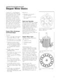
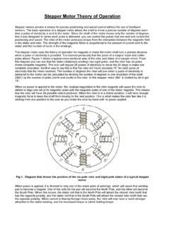
3 When the software is started you may be presented with the following dialog but if not don t worry. Figure 1: Hardware plugin. Since we are going to use the computers printer port as the electrical interface between the computer and our machine we make sure that the Normal Printer Port Operation mode is selected and since we don t want to tell Mach3 this information each time we start the software we put a checkmark in the box next to Don t mask me this again and then click OK. 2 Metric or imperial. The next thing we need to do is to select the native units of choice.
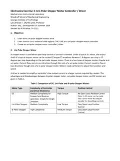
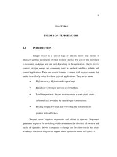
4 To do this we go to the Config menu and click Select Native Units and select either inches or mm and click OK. Since I m a metric guy I choose mm. Figure 2: Default Units Please note that, as the message says before you get to the windows in figure 2, this selection is not for switching the actual displayed coordinates between inches and mm nor is it meant to switch between running part programs written in inches or mm. It is ONLY for setup and tuning of the motors. The hardware interface and connections. Now we need to do is tell Mach3 how many parallel ports and at which addresses they are located.
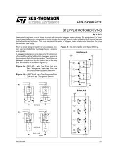
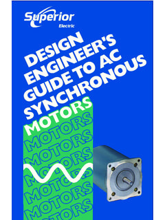
5 If the port is onboard your computers motherboard the standard address is 0x378. But other addresses are sometimes used as well. We tell Mach3 this information by selecting Ports and Pins under the Config Menu. Figure 3: Engine Configuration, Ports & Pins 3 First check that the address of Port#1 corresponds to the actual address of your printer port and that it is enabled. 0x378 is the address most onboard parallel ports use. Since we won t be using a second port here we make sure that Port#2 is disabled. (No checkmark in the Port Enabled box under Port#2).
6 Next thing to do is to select our Kernel speed. This is the frequency at which the Mach3 Driver operates and is also the maximum frequency the software will output to your Motor drives. We will use 25000Hz here. Also make sure that none of the options on the right side is enabled and then click Apply. Next in line is the Motor Outputs tab. This is where we tell Mach3 how many motors we want to control and to which pins in our printer port the each Motor Driver is connected. In this case it s three axis, X, Y and Z so we enable those three by making sure that there is a green checkmark in the first column of those axis.
7 The second column sets the pin to which the step input on our Motor drive is connected. In this case the X axis drive step input is connected to pin 2, Y to pin 4 and Z to pin 6. The third column is just like the second but for the drives direction inputs, wired to 3, 5 and 7 on this machine. The actual pin out of your machine may be different. If you have wired it yourself you probably know the pin out and if you bought the machine and/or Driver box please consult the documentation for that particular machine or check with the hardware manufacturer.
8 The setting of the forth and fifth column depends on how the drives are built and how we have them wired. The most common drives uses optically isolated inputs and are usually supplied with a constant +5V DC from the PC. The drives step and direction inputs are then wired to the computers parallel port which internally switches the pin to ground making the current flow thru the LED in the drives opto isolator which in turn makes the drive move the Motor one step. This makes our step-line active low that is it s on when the output is low.
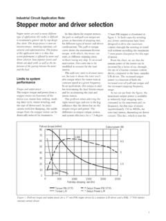
9 Makes any sense? Figure 4: Engine Configuration, Motor Outputs tab. OK, that was the physical connection for the motors. Next thing to take care of would be to set how many steps per unit we have and then go on to actually tune the motors. But before we do that we need to tell the system about one more important thing. 4 The Emergency Stop button. Any decent machine tool should have an Emergency Stop button that, in the safest possible way, halts all machine movement and prevents damage to the operator in the first place and/or the machine so will this one.
10 This tutorial will not go into the actual hardware design of a proper E-stop system but will focus on getting Mach3 to understand that the big red button has been pushed. The various input signals to Mach3 are setup on the Input Signals tab under Ports and Pins in the Config menu: Figure 5: Engine Configuration, Input Signals tab. About halfway down the list we should be able to find the EStop signal, make sure it is enabled. In this case the hardware is wired in such way that the input is brought high when the switch is pushed so the Active Low setting should not be active.