Transcription of Industrial Circuits Application Note Stepper Motor Basics
1 1A Stepper Motor is an electromechanicaldevice which converts electrical pulses intodiscrete mechanical movements. The shaftor spindle of a Stepper Motor rotates indiscrete step increments when electricalcommand pulses are applied to it in theproper sequence. The motors rotation hasseveral direct relationships to these appliedinput pulses. The sequence of the appliedpulses is directly related to the direction ofmotor shafts rotation. The speed of themotor shafts rotation is directly related tothe frequency of the input pulses and thelength of rotation is directly related to thenumber of input pulses Motor Advantagesand DisadvantagesAdvantages1. The rotation angle of the Motor isproportional to the input The Motor has full torque at stand-still (if the windings are energized)3.
2 Precise positioning and repeat-ability of movement since goodstepper motors have an accuracy of3 5% of a step and this error isnon cumulative from one step tothe Excellent response to starting/ Very reliable since there are no con-tact brushes in the the life of the Motor issimply dependant on the life of The motors response to digitalinput pulses provides open-loopcontrol, making the Motor simplerand less costly to It is possible to achieve very lowspeed synchronous rotation with aload that is directly coupled to A wide range of rotational speedscan be realized as the speed isproportional to the frequency of theinput Resonances can occur if notproperly Not easy to operate at extremelyhigh Loop OperationOne of the most significant advantagesof a Stepper Motor is its ability to beaccurately controlled in an open loopsystem.
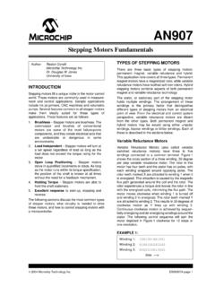
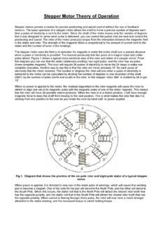
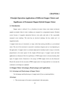
3 Open loop control means nofeedback information about position isneeded. This type of controleliminates the need for expensivesensing and feedback devices such asoptical encoders. Your position isknown simply by keeping track of theinput step Motor TypesThere are three basic Stepper motortypes. They are : Variable-reluctance Permanent-magnet HybridVariable-reluctance (VR)This type of Stepper Motor has beenaround for a long time. It is probablythe easiest to understand from astructural point of view. Figure 1shows a cross section of a typical Motor . This type of motorconsists of a soft iron multi-toothedrotor and a wound stator. When thestator windings are energized with DCcurrent the poles become occurs when the rotor teethare attracted to the energized Magnet (PM)Often referred to as a tin can or canstock Motor the permanentmagnet step Motor is a low cost andlow resolution type Motor with typicalstep angles of to 15.
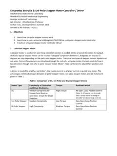
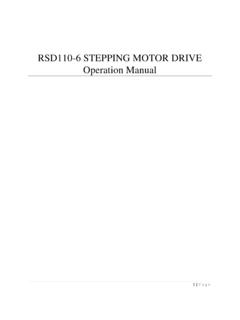
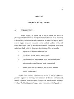
4 (48 24steps/revolution) PM motors as theFigure 1. Cross-section of a variable-reluctance (VR) Circuits Application NoteStepper Motor BasicsFigure 2. Principle of a PM or tin-canstepper 3. Cross-section of a hybrid ABCDA'B'C'D'165432 NSSNNNSNSNNNSS2name implies have permanentmagnets added to the Motor rotor no longer has teeth as withthe VR Motor . Instead the rotor ismagnetized with alternating northand south poles situated in a straightline parallel to the rotor shaft. Thesemagnetized rotor poles provide anincreased magnetic flux intensity andbecause of this the PM Motor exhibitsimproved torque characteristics whencompared with the VR (HB)The hybrid Stepper Motor is moreexpensive than the PM Stepper motorbut provides better performance withrespect to step resolution, torque andspeed.
5 Typical step angles for the HBstepper Motor range from to (100 400 steps per revolution). Thehybrid Stepper Motor combines thebest features of both the PM and VRtype Stepper motors. The rotor ismulti-toothed like the VR Motor andcontains an axially magnetized con-centric magnet around its shaft. Theteeth on the rotor provide an evenbetter path which helps guide themagnetic flux to preferred locations inthe airgap. This further increases thedetent, holding and dynamic torquecharacteristics of the Motor when com-pared with both the VR and two most commonly used typesof Stepper motors are the permanentmagnet and the hybrid types. If adesigner is not sure which type willbest fit his applications requirementshe should first evaluate the PM type asit is normally several times less expen-sive.
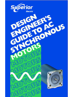
6 If not then the hybrid Motor maybe the right also excist some specialstepper Motor designs. One is the discmagnet Motor . Here the rotor isdesigned sa a disc with rare earthmagnets, See fig. 5 . This Motor typehas some advantages such as very lowinertia and a optimized magnetic flowpath with no coupling between thetwo stator windings. These qualitiesare essential in some and PowerIn addition to being classified by theirstep angle Stepper motors are alsoclassified according to frame sizeswhich correspond to the diameter ofthe body of the Motor . For instance asize 11 Stepper Motor has a body di-ameter of approximately a size 23 Stepper Motor has abody diameter of inches (58 mm),etc. The body length may however,vary from Motor to Motor within thesame frame size classification.
7 As ageneral rule the available torque out-put from a Motor of a particular framesize will increase with increased levels for IC-driven steppermotors typically range from below awatt for very small motors up to 10 20 watts for larger motors. The maxi-mum power dissipation level orthermal limits of the Motor are seldomclearly stated in the Motor manu-facturers data. To determine this wemust apply the relationship P =V example, a size 23 step Motor maybe rated at 6V and 1A per , with two phases energizedthe Motor has a rated power dissipa-tion of 12 watts. It is normal practiceto rate a Stepper Motor at the powerdissipation level where the Motor caserises 65 C above the ambient in stillair.
8 Therefore, if the Motor can bemounted to a heatsink it is oftenpossible to increase the allowablepower dissipation level. This isimportant as the Motor is designed tobe and should be used at its maximumpower dissipation ,to be efficient froma size/output power/cost point of to Use a StepperMotorA Stepper Motor can be a good choicewhenever controlled movement isrequired. They can be used to advan-tage in applications where you need tocontrol rotation angle, speed, positionand synchronism. Because of the in-herent advantages listed previously, Stepper motors have found their placein many different applications. Someof these include printers, plotters,highend office equipment, hard diskdrives, medical equipment, faxmachines, automotive and many Rotating Magnetic FieldWhen a phase winding of a steppermotor is energized with current amagnetic flux is developed in thestator.
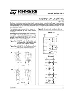
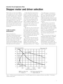
9 The direction of this flux isdetermined by the Right HandRule which states: If the coil is grasped in the righthand with the fingers pointing in thedirection of the current in the winding(the thumb is extended at a 90 angleto the fingers), then the thumb willpoint in the direction of the magneticfield. Figure 5 shows the magnetic fluxpath developed when phase B is ener-gized with winding current in thedirection shown. The rotor then alignsitself so that the flux opposition isminimized. In this case the motorwould rotate clockwise so that itssouth pole aligns with the north poleof the stator B at position 2 and itsnorth pole aligns with the south poleof stator B at position 6. To get themotor to rotate we can now see thatwe must provide a sequence ofenergizing the stator windings in sucha fashion that provides a rotatingmagnetic flux field which the rotorfollows due to magnetic GenerationThe torque produced by a steppermotor depends on several factors.
10 The step rate The drive current in the windings The drive design or typeIn a Stepper Motor a torque is devel-oped when the magnetic fluxes of therotor and stator are displaced fromeach other. The stator is made up of ahigh permeability magnetic presence of this high permeabilitymaterial causes the magnetic flux tobe confined for the most part to thepaths defined by the stator structurein the same fashion that currents areconfined to the conductors of an elec-tronic circuit. This serves to concen-trate the flux at the stator poles. TheFigure 4. Principle of a disc magnet motordeveloped by 5. Magnetic flux path through atwo-pole Stepper Motor with a lag betweenthe rotor and 6. Unipolar and bipolar woundstepper output produced by the motoris proportional to the intensity of themagnetic flux generated when thewinding is basic relationship whichdefines the intensity of the magneticflux is defined by:H = (N i) lwhere.