Transcription of Determining MOSFET Driver Needs for Motor Drive …
1 2003 Microchip Technology 1 MAN898 INTRODUCTIONE lectronic Motor control for various types of motorsrepresents one of the main applications for MOSFET drivers today. This application note discusses some ofthe fundamental concepts needed to obtain the properMOSFET Driver for your bridging element between the Motor and MOSFET Driver is normally in the form of a power transistor. Thiscan be a bipolar transistor, MOSFET or an InsulatedGate Bipolar Transistor (IGBT). In some smallBrushless DC Motor or stepper Motor applications, theMOSFET Driver can be used to directly Drive the this application note, though, we are going toassume that a little more voltage and power capabilityis needed than what the MOSFET drivers can purpose of Motor speed control is to control thespeed, direction of rotation or position of the motorshaft. This requires that the voltage applied to themotor is modulated in some manner. This is where thepower-switching element (bipolar transistor, MOSFET ,IGBT) is used.
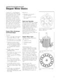
2 By turning the power-switching ele-ments on and off in a controlled manner, the voltageapplied to the Motor can be varied in order to vary thespeed or position of the Motor shaft. Figures 1through 5 show diagrams of some typical Drive config-urations for DC Brush, DC Brushless, stepper , SwitchReluctance and AC Induction 1: Drive Configuration for a DC Brush 2: Drive Configuration for a DC Brushless 3: Drive Configuration for a 4-Wire stepper :Jamie DunnMicrochip Technology +-MotorVSUPPLY+-MotorVSUPPLY+-MotorDeter mining MOSFET Driver Needs for Motor Drive ApplicationsAN898DS00898A-page 2 2003 Microchip Technology 4: Drive Configuration for Each Winding of a Switch Reluctance 5: Drive Configuration for an AC Induction seen in Figures 1 through 5, even though the motortype changes, the purpose of the Drive circuitry is toprovide voltage and current to the windings of themotor. The voltage and current level will varydepending on what type and size of Motor is beingused, but the fundamentals of selecting the power-switching element and the MOSFET Driver are THE POWER-SWITCHING ELEMENTThe first stage in selecting the correct power-switchingelement for your Motor Drive application isunderstanding the Motor being driven.
3 Understandingthe ratings of the Motor is an important step in theprocess as it is often the corner points of operation thatwill determine the choice of the power switchingelement. A sample of Motor ratings for the Motor typeslisted earlier is shown in Table 1. When dealing withmotors, it is often useful to remember that 1 HorsePower (HP) is equal to 746 the ratings in Table 1, the voltage, current andpower ratings vary significantly with the different typesof motors. Motor ratings can also vary significantlywithin the same Motor type. A key point to note inTable 1 is the value of the start-up current (sometimesgiven as stall current or locked-rotor current). Thestartup current value can be up to three times the valueof the steady-state operating current. As mentionedpreviously, it is these corner points of operation that willdetermine the necessary ratings of the Drive of the various voltage and current ratings forthe various Motor types, the selected Drive deviceratings will have to vary as well, depending on theapplication and design +-MotorVSUPPLY+-MotorTABLE 1: Motor RATINGSM otor TypeHorse Power Rating (HP)Voltage RatingCurrent Rating (A)Efficiency(%)Power FactorSlip FactorTorquelb*ftFull Load RPMFullLoadLockedRotorDC to 600 Switch ,000AC 2003 Microchip Technology 3AN898 MOSFET OR IGBT, WHAT S BEST FOR YOUR APPLICATION?
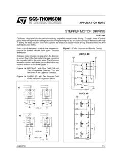
4 The two main choices for power-switching elements formotor drives are the MOSFET and IGBT. The bipolartransistor used to be the device of choice for motorcontrol due to it s ability to handle high currents andhigh voltages. This is no longer the case. The MOSFETand IGBT have taken over the majority of the applica-tions. Both the MOSFET and IGBT devices are voltagecontrolled devices, as opposed to the bipolar transistor,which is a current-controlled device. This means thatthe turn-on and turn-off of the device is controlled bysupplying a voltage to the gate of the device, instead ofa current. This makes control of the devices 6: MOSFET and IGBT similarities between the MOSFET and the IGBTend with the turn-on and turn-off of the devices beingcontrolled by a voltage on the gate. The rest of theoperation of these devices is very different. The maindifference being that the MOSFET is a resistivechannel from drain-to-source, whereas the IGBT is aPN junction from collector-to-emitter.
5 This results in adifference in the way the on-state power dissipationsare calculated for the devices. The conduction lossesfor these devices are defined as follows:The key difference seen in these two equations forpower loss is the squared term for current in theMOSFET equation. This requires the RDS-ON of theMOSFET to be lower, as the current increases, in orderto keep the power dissipation equal to that of the low voltage applications, this is achievable as theRDS-ON of mosfets can be in the 10 s of higher voltages (250V and above), the RDS-ON ofMOSFETs do not get into the 10 s of key point when evaluating on-state losses isthe temperature dependence of the RDS-ON of theMOSFET versus the VCE-SAT of an IGBT. Astemperature increases, so does the RDS-ON of theMOSFET, while the VCE-SAT of the IGBT tends todecrease (except at high current). This means anincrease in power dissipation for the MOSFET and adecrease in power dissipation for the all of this into account, it would seem that theIGBT would quickly take over the applications of theMOSFET at higher voltages, but there is anotherelement of power loss that Needs to be is the losses due to switching.
6 Switching lossesoccur as the device is turned on and off with currentramping up or down in the device with voltage fromdrain-to-source ( MOSFET ) or collector-to-emitter(IGBT). Switching losses occur in any hard-switchedapplication and can often dominate the power losses ofthe switching IGBT is a slower switching device than theMOSFET and, therefore, the switching losses will behigher. An important point to note at this juncture is thatas IGBT technology has progressed over the past 10years, various changes have been made to improvethe devices with different applications. This is also trueof mosfets , but even more so for IGBTs. Variouscompanies have multiple lines of IGBTs. Some areoptimized for slow-speed applications that have lowerVCE-SAT voltages, while others are optimized forhigher-speed applications (60 kHz to 150 kHz) thathave lower switching losses, but have higher VCE-SATvoltages. The same is true for mosfets .
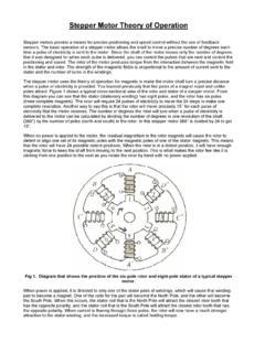
7 Over the past5 years, a number of advances have been made inMOSFET technology which have increased the speedof the devices and lowered the RDS-ON. The net resultof this is that, when doing a comparison between IGBT sand mosfets for an application, make sure thedevices being compared are best suited to theapplication. This assumes, of course, that the devicesalso fit within your the IGBT is slower than the MOSFET at bothturn-on and turn-off, it is mainly the turn-off edge that isslower. This is due to the fact that the IGBT is a minoritycarrier recombination device in which the gate of thedevice has very little effect in driving the device off (willvary depending on the version of the IGBT, fast, ultra-fast, etc.). This can be seen in the equivalent circuit forthe IGBT shown in Figure 7. When the gate is turnedon (driven high), the N-channel MOSFET pulls low onMOSFETPLOSS = Irms2 * RDS-ONwhere:RDS-ON = drain-to-source on-state resistanceIrms = drain-to-source rms currentIGBTPLOSS = Iave * VCE-SATVCE-SAT = collector-to-emitter saturation voltageIave = collector-to-emitter average currentN-ChannelMOSFETN-Channel IGBTCEGDSGAN898DS00898A-page 4 2003 Microchip Technology base of the PNP transistor, effectively driving thedevice on.
8 During turn-off, however, when the gate ofthe device is pulled low, only the minority carrier recom-bination of the device is effecting the turn-off speed. Byvarying some of the parameters of the device (such asoxide thickness and doping) the speed of the devicecan be changed. This is the essence of the variousfamilies of IGBTs that are available from multiple sup-pliers. Increases in speed often result in higher VCE-SATvoltages and reduced current ratings for a given 7:Equivalent Circuit for an switching losses for IGBTs is not asstraightforward as it is for the MOSFET . For this rea-son, switching losses for IGBTs are typically character-ized in the device data sheet. Switching losses aretypically given in units of Joules. This allows the user tomultiply the value by frequency in order to get losses is the biggest limiting factor that keepIGBTs out of many high-voltage, high switching-fre-quency applications.
9 Because of the relatively lowmodulation/switching frequencies of Motor controlapplications (typically less than 50 kHz), the switchinglosses are kept in check and the IGBT is as good orbetter than the this application note does not cover all the prosand cons of mosfets versus IGBTs, listed below areother application notes written about this topic. IGBTs vs. HEXFET Power mosfets For Variable Frequency Motor Drives , AN980, International Rectifier. Application Characterization of IGBTs (this one will help you apply the IGBT and understand the device), AN990, International Rectifier. IGBT Characteristics . This one goes into the fundamentals of the IGBT and compares it with the MOSFET , AN983, International Rectifier. IGBT or MOSFET : Choose Wisely . This one discusses the crossover region of applications based on voltage rating of the device and operating frequency, White Paper, International Rectifier. IGBT Basic II . This application note covers IGBT basics and discusses IGBT gate Drive design and protection circuits, AN9020, Fairchild Semiconductor.
10 Application Manual from Fuji Semiconductor for their 3rd-Generation IGBT modules. This covers many topics from IGBT basics to current summarize some of the discussion so far, some ofthe generally accepted boundaries of operation whencomparing the IGBT and MOSFET are: For application voltages < 250V, mosfets are the device of choice. In searching many IGBT suppliers, you will find that the selection of IGBTs with rated voltages below 600V is very small. For application voltages > 1000V, IGBTs are the device of choice. As the voltage rating of the MOSFET increases, so does the RDS-ON and size of the device. Above 1000V, the RDS-ON of the MOSFET can no longer compete with the saturated junction of the IGBT. Between the 250V and 1000V levels described above, it becomes an application-specific choice that revolves around power dissipation, switching frequency and cost of the evaluating the MOSFET versus the IGBT for anapplication, be sure to look at the performance of thedevice over the entire range.