Transcription of Industrial Circuit Application Note Stepper motor and ...
1 1In data sheets for Stepper motors,the pull-in and pull-out torque aregiven, as functions of stepping rate,for different types of motor and drivercombinations. The pull-in torquecurve shows the maximum frictiontorque with which, the motor canstart, at different stepping rates,without losing any step. In an actualapplication, this curve has to bemodified to account for the pull-out curve is of more inter-est, because it shows the total avail-able torque when the motor runs atconstant speed at a given an Application , this torque is usedfor overcoming the load fiction torqueand for accelerating the load andmotor problem when selecting theright motor type and size is the biginfluence that the driver has on theoutput torque and power.
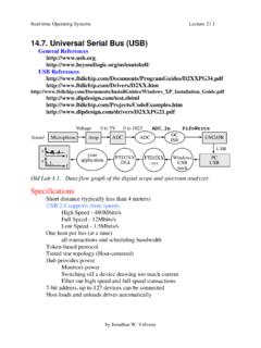
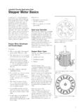
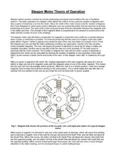
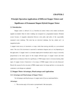
2 Thedifference in output torque, power,and system efficiency for a PM Stepper is illustrated infigure 1. In both cases the windingand driver combination have beendesigned to drive the maximumcurrent through the winding at standstill without exceeding the maximum7-watt power dissipation for this typeof the chart, we see that theoutput power of the motor can beincreased by a factor of six, throughthe use of a bipolar constant currentdriver, compared to the basic unipolarL/R-driver. The increased outputpower is a function of both theincreased over-all pull-out torque andthe increased stepping we can see from the figure, themaximum output power is availableat relatively high stepping rates,compared to the maximum pull-infrequency, for this type of motor (approximately 150 to 400Hz, forzero-load inertia, depending on drivercircuit).
3 This fact, which is true forStepper motors are used in many differenttypes of applications this makes it difficultto recommend a general step-by-step designflow chart. The design process is more aniterative process, involving experience, cal-culation and experimentation. The purposeof this Application note is to show howsystem performance is affected by motor anddriver selection. Some popular motors anddrivers are dealt with, as well as the im-portance of the gearing between the motorand the to systemperformanceTorque and output powerThe output torque and power from astepper motor are functions of themotor size, motor heat sinking, work-ing duty cycle, motor winding, andthe type of driver used. In appli-cations with low damping, the usabletorque from the Stepper motor can bedrastically reduced by Circuit Application NoteStepper motor and driver selection0102030405060708005001000150020 002500 Torque PBL3770:Torque L/ROutput Power PBL3770:Output Power L/RFull-step stepping rate [Hz]Output power [W]Pull-out torque [mNm]01,534, 1.
4 Pull-out torque and output power for a 57 mm PM Stepper driven by a unipolar L/R-driver and a PBL 3770A bipolarconstant current Stepper applications, shows that,to be able to get a high-performancestepper motor system, we have to useramping up/down when we start andstop the motor and load. The use oframping opens up Stepper motors forpower output applications, and doesnot limit the usage of steppers to low-performing low-output power and resonancesIn applications with low systemdamping, the available output torqueand power can be drastically reducedby resonance. Resonances in steppermotor systems can arise at low-, mid-,and high stepping rates. As a rule,constant current drivers have the mostproblems with resonances in the low-frequency region.
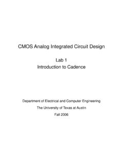
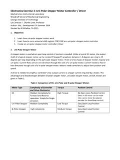
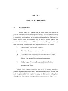
5 These resonancescan often be eliminated by using half-stepping or microstepping. Constantvoltage drivers normally have problemswith resonances at medium and/orhigh frequencies. At these frequen-cies, neither half- nor microsteppingcan reduce the resonances. This limitsthe usage of this type of drivers atmedium and high frequencies todriving high-damping also depends on themotor type PM-motors have higherdamping than hybrids, due to slideFigure 2. Performance curves for a 100ohm unipolar 57 mm PM- motor drivenby a 20V L/R constant voltage driver. Lowest motor output power. Maximum power dissipation atstand still. Higher motor cost and larger sizefor the same output power as fromother drives. Driver transistors have to withstandtwice the maximum supply voltage.
6 Windings must be designed for theused supply voltage. Regulated power supply normallyrequired. Holding torque depends on supplyvoltage and motor temperature. Large torque ripple when driven inhalf-step mode. Low electronic component cost. For small motors very low costtransistor arrays can be used. Low electrical noise friction and magnetic driver and motor combina-tions have such low damping, atcertain stepping rates, that they donot run without a high-damping condition is known as and positioning accuracyThe resolution of a Stepper motorsystem is affected by several factors the Stepper motor full-step length,the selected driver mode (full-step,half-step or microstepping), and thegear rate.
7 This means that there areseveral different combinations whichcan be used to get the desired resolu-tion. Because of this, the resolutionproblem of a Stepper design cannormally be dealt with after themotor size and driver type have timeEven though customization of stepmotors is possible, it requires bothengineering time and time for manu-facturing Stepper motor a more-flexible driver Circuit ,like the chopper constant currentdriver can make it possible to select astandard motor with no performanceloss. Low speed and low power applica-tions were the motor mainly isused to produce a torque. Normally only used with small 1. Unipolar constant voltage driver attributesFeaturesDrawbacksApplications0 1020304050607080050010001500 Pull-out TorqueEfficiencyOutput PowerFull-step stepping rate [Hz]Pull-out torque [mNm]Efficiency [%]Output power [W] is no-load unstable for stepping rates above high-volume applications, the majorcost is the hardware includingpower supply, driver, wiring, motor ,and gearing.
8 In this case, the engine-ering cost is less important. In manyapplications, it is possible to lower thetotal system cost and increase theperformance by using a more-complexdriver (with a slightly higher cost) andless-costly motor and power low- and medium-volume appli-cations, the engineering cost becomesa larger part of the total cost. In thiscase the flexibility and high integra-tion of a constant current driver canhelp save engineering time and characteristicsIn applications were the Stepper mustmove from one position to anotherthen stop in the shortest possibletime, the settling time becomes a veryimportant factor. If the system isdesigned properly, the settling timecan be kept to a minimum if not,the settling time can easily requireseveral hundred get good dynamic behavior inan open loop system, it is importantto have the correct gear rate andprecise control of the motor runningand holding torque.
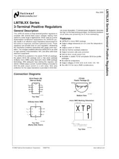
9 With well-designed gearing, it is possible tohandle variations in both load inertiaand of driversIn the following section, the perfor-mance of some commonly-used driverconfigurations are compared whenthey drive a 57mm PM- Stepper motor . Driving voltage/currents are selected so the stand-stillmotor losses are kept at maximumrated 7 W. The performance curvesshow the pull-out torque, outputpower (at the motor shaft), and thesystem efficiency. Efficiency is definedas the mechanical output power fromthe motor divided by the input powerto the driver. For each driver, featuresand drawbacks are also constant voltageThis is the classic low-end driver. Itoffers the lowest price for the driverelectronics only four transistors areused.
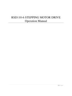
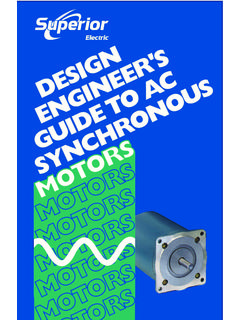
10 To drive small-sized motors, atransistor array of ULN 2003 orsimilar type can be used. For mid-sized motors, power darlingtontransistors, or transistor arrays can beused. In figure 2, the performance ofthis type of driver is shown. A motorwinding with 100 ohm phaseresistance has been selected. Thisgives good control of winding currentand low losses in power this driver, the motor hasproblems with no-load instabilities atstepping rates above 3. Performance curves for a 100ohm unipolar 57mm PM- motor driven bya 40V L/2R constant-voltage driver(2 100ohm external series resistors).Table 2. Unipolar L/NR constant voltage driver attributesFeaturesDrawbacksApplications Low component cost Low electrical noise level.