Transcription of CHAPTER 2 THEORY OF STEPPER MOTOR 2.1 …
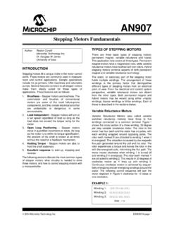
1 11 CHAPTER 2 THEORY OF STEPPER MOTOR INTRODUCTION STEPPER MOTOR is a special type of electric MOTOR that moves in precisely defined increments of rotor position (Steps). The size of the increment is measured in degrees and can vary depending on the application. Due to precise control, STEPPER motors are commonly used in medical, satellites, robotic and control applications. There are several features common to all STEPPER motors that make them ideally suited for these types of applications. They are as under High accuracy: Operate under open loop Reliability: STEPPER motors are brushless. Load independent: STEPPER motors rotate at a set speed under different load, provided the rated torque is maintained. Holding torque: For each and every step, the MOTOR holds its position without brakes. STEPPER MOTOR requires sequencers and driver to operate.
2 Sequencer generates sequence for switching which determines the direction of rotation and mode of operation. Driver is required to change the flux direction in the phase windings. The block diagram of STEPPER MOTOR system is shown in Figure 12 Figure Block diagram of STEPPER MOTOR system TYPES OF STEPPER MOTORS It can be classified into several types according to machine structure and principle of operation as explained by Kenjo (1984). Basically there are three types 1. Variable Reluctance MOTOR (VRM) 2. Permanent Magnet STEPPER MOTOR (PMSM) 3. Hybrid STEPPER MOTOR (HSM) Variable Reluctance MOTOR It consists of a soft iron multi-toothed rotor and a wound stator. When the stator windings are energized with DC current, the poles become magnetized. Rotation occurs when the rotor teeth are attracted to the energized stator poles.
3 Both the stator and rotor materials must have high permeability and be capable of allowing high magnetic flux to pass through even if a low magneto motive force is applied. When the rotor teeth are directly lined up with the stator poles, the rotor is in a position of minimum reluctance to the magnetic flux. Driver Circuit Sequencer STEPPER MOTOR Power Supply 13 A rotor step takes place when one stator phase is deenergized and the next phase in sequence is energized, thus creating a new position of minimum reluctance for the rotor as explained by Kenjo (1984). Cross-section of variable reluctance MOTOR is shown in Figure Figure Cross-section of variable reluctance MOTOR Permanent Magnet STEPPER MOTOR A STEPPER MOTOR using a permanent magnet in the rotor is called a PMSM.
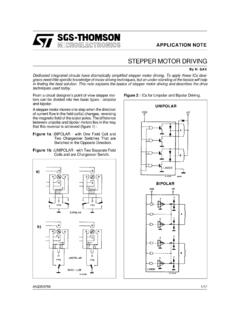
4 The rotor no longer has teeth as with the VRM. Instead the rotor is magnetized with alternating north and south poles situated in a straight line parallel to the rotor shaft. These magnetized rotor poles provide an increased magnetic flux intensity and, because of this the PM MOTOR exhibits improved torque characteristics when compared with the VRM type. An elementary PM MOTOR is shown in Figure which employs a cylindrical permanent magnet as the rotor and possesses four poles in its stator. Two overlapping windings are wound as one winding on poles 1 and 3 and these two windings are separated from each other at terminals to keep them as independent windings. The same is true for poles 2 and 4. The terminals marked Ca or Cb denotes connected to the positive terminal of the power supply as explained by Kenjo (1984).
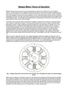
5 14 When the windings are excited in the sequence A - B - A1 - B1 --- the rotor will be driven in a clockwise direction. The step length is 900 in this machine. If the number of stator teeth and magnetic poles on the rotor are both doubled, a two-phase MOTOR with a step length of 450 will be realized. Figure Cross-section of permanent magnet STEPPER MOTOR Hybrid STEPPER MOTOR is derived from the fact that MOTOR is operated with the combined principles of the permanent magnet and variable reluctance motors in order to achieve small step length and high torque in spite of MOTOR size. Standard HSM have 50 rotor teeth and rotate at degree per step. Figures & show a cross section and cut view of two phase HSM. The windings are placed on the stator poles and a PM is mounted on the rotor.
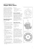
6 The important feature of the HSM is its rotor structure. A cylindrical or disk-shaped magnet lies in the rotor core. Stator and rotor end-caps are toothed. The coil in pole 1 and pole 3 is connected in series consisting of phase A and poles 2 and 4 are for phase B. If stator phase A is excited pole 1 acquires north polarity while pole 2 acquires south south pole while pole 3 aligns north pole. 15 Figure Cross-section of HSM Figure Cut view of HSM When the excitation is shifted from phase A to phase B, in which case the stator pole 2 becomes north pole and stator pole 4 becomes south pole, it would cause the rotor to turn 900 in the clockwise direction. Again phase A is excited with pole 1 as south pole and pole 3 as north pole causing the rotor to move 900 in the clockwise direction.
7 Rotor -1 Shaft Rotor -2 Stator -1 Coil Winding End cap End cap Bearing Permanent magnet 16 If excitation is removed from phase A and phase B is excited, then pole 2 produces south pole and pole 4 produces north pole resulting in rotor movement of 900 in the clockwise direction. A complete cycle of excitation for the HSM consists of four states and produces four steps of rotor movement. The excitation state is the same before and after these four steps and hence the alignment of stator/rotor teeth occurs under the same stator poles as explained by Kenjo (1984). The step length for a HSM and angle through which the rotor moves for each step pulse is known as step angle and is calculated by Step length = 90o/Nr ( ) Step angle is calculated using the formula ( ) Where - Step angle in degrees - Number of stator teeth - Number of rotor teeth - Number of phases Mechanical angle represents the step angle of the step.
8 In the full step mode of a MOTOR , the mechanical angle is . In the 10 micro step mode of a MOTOR , the mechanical angle is . An electrical angle is defined as 360 divided by the number of mechanical phases and the number of micro step. In the full step mode of a MOTOR , the electrical angle is 90 . In the 10 micro step excitation of a MOTOR , the electrical angle is 9 . HSM material properties for each part and standard step angle of HSM are tabulated in Table and Table respectively. 17 Table Material properties of HSM MOTOR Part Material 1. Shaft Non-Magnetic material 2. Magnet Neodymium Iron Boron (NdFe) / Samarium Cobalt (SMCO5) 3. Rotor core Steel sheet 4. Stator core Steel sheet 5. Coil Copper Table Standard step angle of HSM Step angle Steps per revolution 400 200 100 50 15 24 18 Advantages and disadvantages of HSM are discussed by Acarnely (2002) and in a nutshell, they are as here below a.
9 Advantages 1. Step angle error is very small and non-cumulative. 2. Rapid response to starting, stopping and reversing. 3. Brushless design for reliability and simplicity. 4. High torque per package size. 5. Holding torque at standstill. 6. Can be stalled repeatedly and indefinitely without damage. 7. No extra feedback components required (encoders). b. Disadvantages 1. Resonance 2. Vibration 3. Torque ripple COMPARISON OF STEPPER MOTOR TYPES The choice of the type of the STEPPER MOTOR depends on the application. Selection of STEPPER MOTOR depends on torque requirements, step angle and control technique. 19 The complexity of the controller circuits are explained detail by Athani (2005). Comparisons based on MOTOR advantages and disadvantages, MOTOR characteristics and different phases are tabulated in Tables ( - ).
10 Table Comparison based on MOTOR advantages and disadvantages MOTOR type Advantages Disadvantages Variable Reluctance MOTOR 1. Robust No magnet 2. Smooth movement due to no cogging torque. 3. High stepping rate and speed slewing capability. 1. Vibrations 2. Complex circuit for control 3. No smaller step angle 4. No detent torque. Permanent Magnet STEPPER MOTOR 1. Detent torque 2. Higher holding torque 3. Better damping 1. Bigger step angle 2. Fixed rated torque. 3. Limited power output and size Hybrid STEPPER MOTOR 1. Detent torque 2. No cumulative position error 3. Smaller step angle 4. Operate in open loop 1. Resonance 2. Vibration 20 Table Comparison based on MOTOR characteristics Specifications MOTOR types VRM PMSM HSM Step angle 30 45 5 Phases 3,4,5 2,4 2,5 Drive type Unipolar Unipolar/Bipolar Bipolar Rotor inertia Low High Medium Table Comparison based on different phase properties Type of Phases Properties 2 phase 1.