Transcription of Electronics Exercise 3: Uni-Polar Stepper Motor Controller ...
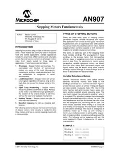
1 Electronics Exercise 3: Uni-Polar Stepper Motor Controller / Driver Mechatronics Instructional Laboratory Woodruff School of Mechanical Engineering Georgia Institute of Technology Lab Director: I. Charles Ume, Professor Author: Kita , Development TA Summer 2004 Revised by Ali AlSaibie, TA 2015. 1. Objectives 1. Learn how Uni-Polar Stepper motors work 2. Learn how to use a universal shift register (74LS194) as a Uni-Polar Stepper Motor Controller 3. Create an Uni-Polar Stepper Motor Controller /driver 2. Uni-Polar Stepper Motor A Stepper Motor is used when open loop control of position is needed. Unlike a typical DC Motor , the output shaft of a typical Stepper Motor can be rotated ( stepped ) anywhere between degrees per step to 15 degrees per step depending on the particular Stepper Motor .
2 There are two types of Stepper motors: bipolar and Uni-Polar . Current flows only in one direction through the coils of a Uni-Polar Motor . Current needs to flow in two directions though coils of a bi- polar Stepper Motor . Motors need controllers to adjust their position and speed. A driver is needed to amplify a Controller s low output current to a larger current required by a Motor . The advantages and disadvantages between bi- polar Stepper Motor , Uni-Polar Stepper Motor , and DC motors are given in Table 1. Table 1 Comparison of DC, Uni-Polar and Bi- polar Stepper Motors Motor Type Complexity of Controller and Driver Electronics Torque Position Control DC Medium Complexity for Forward and Reverse operation. Simple for Single Direction High Torque No Open Loop Position Control (Note: A DC Motor can be made into a servo Motor by using an encoder for closed loop control).
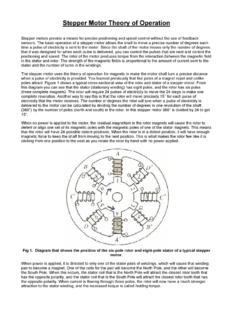
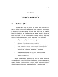
3 Uni-Polar Stepper Medium Complexity Low Torque Easy Open Loop Position Control Bi- polar Stepper High Complexity Medium Torque Easy Open Loop Position Control A Uni-Polar Stepper Motor will be used in this Exercise . A simplified diagram of a Uni-Polar Stepper Motor is shown in Figure 1. Figure 1 Diagram of Uni-Polar Stepper Motor The Uni-Polar Stepper Motor shown in Figure 1 has a 45 degree per step configuration. The rotor will point to the closest coil with power applied to it. The rotor will rotate counter clockwise if coils A1, B1, A2, B2, A1, B1, etc. are energized in sequence. The rotor will rotate clockwise if coils A1, B2, A2, B1, A1, B2, are energized in sequence. Another set of A1,B1,A2, and B2 coils will produce a 30 degree per step configuration.
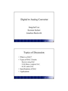
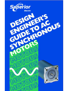
4 Two additional sets of A1,B1,A2, and B2 coils will produce a degree per step configuration. More sets of A1, B1, A2, and B2 coils will produce even finer degrees per step configurations. The schematic symbol for a Uni-Polar Stepper Motor regardless of degree per step is given in Figure 2 Figure 2 Schematic Symbol for Uni-Polar Stepper Motor There are a many ways of energizing Stepper Motor coils in the proper sequence. A microcontroller may be used as a Uni-Polar Stepper Motor Controller but this will take memory and processing time. This is especially true in final projects where three or more Stepper motors are used. It would be advantageous to make a Uni-Polar Stepper Motor Controller circuit. Inputs into a Uni-Polar Stepper Motor Controller circuit should be when to step and which direction to turn.
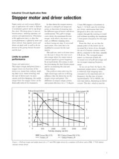
5 This can be accomplished using a universal shift register as a Controller . 3. Universal Shift Register (74LS194) as a Uni-Polar Stepper Motor Controller The universal shift register is a standardized logic chip (74LS194) manufactured by various companies. The universal shift register pinout is shown in Figure 3. Figure 3 Universal Shift Register (74LS194) Pin out Table 2 74LS194 Pinout Pin Name Description 1 CLR Clear Output Pin 2 SR Serial Shift Right Input Pin 3 A Parallel Shift Input Pins 4 B 5 C 6 D 7 SL Serial Shift Left Input Pin 8 GND Logic Ground 9 S0 Model Select Pins 10 S1 11 CLK Clock Input Pin 12 QD Output Pins 13 QC 14 QB 15 QA 16 Vcc 5V Logic Power Supply The operation of the chip is summarized in Table 3 Table 3: Operation of Universal Shift Register (L 0V, H-5V, X-does not matter, - transition from 0V 5V) CLR CLK S0 S1 QA QB QC QD Description 1 L X X X L L L L Outputs Cleared 2 H X L L QA QB QC QD Outputs Stay the same 3 H L H QB QC QD SL Output Shift Left.
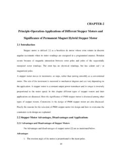
6 Input SL before clock transition is copied to Output QD 4 H H L SR QA QB QC Output Shift Right. Input SR before clock transition is copied to Output QA 5 H H H A B C D Output Parallel Shift. Inputs A, B, C, D copied to Outputs QA, QB, QC, QD The following Figure 4, shows a universal shift register used as an Uni-Polar Stepper Motor Controller . Figure 4 Universal Shift Register as a Uni-Polar Stepper Motor Controller Only CLK, S0, and S1 inputs need to be manipulated in order to control a Uni-Polar Stepper Motor using the circuit in Figure 4. Setting rotation direction and initialization of the circuit is done using inputs S0 and S1. The Stepper Motor steps when there is a transition from 0V to 5V on the clock pin.
7 Therefore, the speed of rotation can be controlled by controlling the number of transitions on the clock pin per second. An example of how to step an Uni-Polar Stepper Motor 6 steps clockwise then 6 steps counter clockwise using the above circuit is shown below in table 3. Table 4 Example of stepping Uni-Polar Stepper Motor using circuit show in Figure 4 (L 0V, H 5V, X does not matter, - transition from 0V to 5V) CLK S0 S1 QA (A1 Coil) QB (B1 Coil) QC (A2 Coil) QD (B2 Coil) Operation (Table 3) Description X X X X X X X Circuit Power On H H H L L L 5 Initialize Controller L H L L L H 3 Clockwise Step 1 L H L L H L 3 Clockwise Step 2 L H L H L L 3 Clockwise Step 3 L H H L L L 3 Clockwise Step 4 L H L L L H 3 Clockwise Step 5 L H L L H L 3 Clockwise Step 6 H L L L L H 4 Counter Clockwise Step 1 H L H L L L 4 Counter Clockwise Step 2 H L L H L L 4 Counter Clockwise Step 3 H L L L H L 4 Counter Clockwise Step 4 H L L L L H 4 Counter Clockwise Step 5 H L H L L L 4 Counter Clockwise Step 6 4.
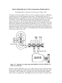
8 Uni-Polar Stepper Motor Driver The power output from a universal shift register is inadequate for energizing coils in a Stepper Motor . Four NPN transistors and diodes are needed to create a Uni-Polar Stepper Motor driver. An NPN transistor has three pins: collector, base, and emitter. The circuit symbol for an NPN transistor is shown in Figure 5 Figure 5 Schematic Symbol for NPN Transistor The NPN Transistor will allow a large current to flow from collector to emitter when there is a smaller current from base to emitter. The schematic for a Uni-Polar Stepper Motor driver using four NPN transistors and diodes is given in Fig. 6. Diodes are used to protect the transistor from reverse currents generated by the Motor .
9 (Note: Transistors will be covered in greater detail during class lectures.) Figure 6 Driver for Uni-Polar Stepper Motor 5. Lab Task Your task is to assemble the circuit shown in Figure 7 on a perforated protoboard. You will also have a Uni-Polar Stepper Motor to test your circuit with. The Bill of Materials is given in 7. The pinouts are given in 8. Figure 7 Schematic of Uni-Polar Stepper Motor Controller /Driver (Transistors have diodes already incorporated) Questions: a) Connect the TTL output pulse of the function generator to Node A in Fig. 7. Connect the ground of the function generator to ground in Fig. 7. The function generator is now acting as the clock input into the Controller . Vary the rotational speed by varying the frequency of the function generator.
10 Slowly increase the rotational speed. At what frequency does the Stepper Motor stop rotating? Why? 6. Lab Deliverables Demonstrate a working circuit setup to your lab instructor in person. And submit your answers to the above questions by the due date. 7. Bill of Materials Note that designations are specific to Figure 7 Designation Description Part No. R1, R2, R3, R4, R5, R6, R7 1k Resistor S1, S2, S3 Push Button (Momentary Switch) T1, T2, T3, T4 NPN transistor - Diode Incorporated ZTX653 U1 74LS194 Counter Shift Registers SN74LS194AN 8. Pinouts and Wirings Stepper Motor Wiring Example Only. Motors differ in configuration. The Stepper Motor wiring is not consistent across all motors. To check the correct wiring configuration, read the resistance across the coils.