Transcription of nPM1100 - Nordic Semiconductor
1 nPM1100 Product / 2021-05-20nPM1100nPM1100 is an integrated Power Management IC (PMIC) with a linear-mode lithium-ion/lithium-polymerbattery charger in a compact mm WLCSP package. It has a highly efficient, dual-mode configurableoutput DC/DC buck is an extremely compact PMIC device, created for space constrained applications with a smalllithium-ion or lithium-polymer battery. It is compatible with all nRF52 and nRF53 Series SoCs and supportscharging batteries at up to 500 mA through USB, and also delivers up to 150 mA of current to powerexternal components with regulated minimum of five passive components are required for operation and the device functions without acontrol interface.
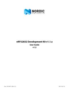
2 It is the perfect companion for nRF52 and nRF53 multiprotocol SoCs in battery powereddesigns. Low quiescent current (IQ) extends battery life during shipping and storage with Ship mode, or inoperation using auto-controlled hysteretic buck mode for high efficiency down to 1 A loads. Charge anderror indication LED drivers are built in. Charge profile limits are configurable and VBUS current limits canbe fixed or auto-controlled with on-chip USB port detection. Ultra-high efficiency prolongs battery life or allows for use of smaller and less costly batteries Small solution size leaves space for additional features without increasing product size No software control Automatic USB port detection minimizes development time+VBATNTCAVSSVBUSSWVOUTBVSYSPVSSCHGER RBATTERY PACKDECICHGVOUTBSET0 VOUTBSET1D+ D-VTERMSETISETMODESHPACTSHPHLDSYSREG System regulatorCHARGER 400 mA Li-Ion chargerBUCK DC/DC regulatorVINTF igure 1: nPM1100 block diagram4445_367 listFeatures.
3 400 mA linear battery charger Linear charger for lithium-ion/lithium-polymer batteries Adjustable charge current from 20 mA to 400 mA Selectable termination voltage of V or V Automatic trickle, constant current, and constant voltage charging Battery thermal protection Discharge current limitation JEITA compliant Li-ion/Li-polymer USB battery charger with a high efficiency buck regulator 800 nA - Typical quiescent current 460 nA - Shipping mode quiescent current Thermal protection Input regulator USB compatible current limit of 100 mA and 500 mA V to V input voltage range for normal operation 20 V overvoltage protection Reverse current protection V to V system voltage output USB port detection supporting the following types.
4 SDP CDP/DCP V to V, 150 mA step-down buck regulator Step-down buck regulator with up to 92% efficiency Automatic transition between hysteretic and pulse widthmodulation (PWM) modes Forced PWM mode for clean power operation Pin-selectable output voltage ( V, V, V, V) Soft start-up LED drivers for charger state indication 5 mA low side LED driver for charging indication 5 mA low side LED driver for error indication V to V battery operating input range mm WLCSP package Suitable for two layer PCB designApplications: Advanced wearables Health/fitness sensor and monitor devices Advanced computer peripherals and I/O devices Mouse Keyboard Multi-touch trackpad Interactive entertainment devices Remote controls Gaming controllers4445_367.
5 IiFeature list..iii1 Revision history..62 About this document.. Document status .. Core component chapters ..73 Product overview.. Block diagram .. In circuit configurations .. System description .. Power-on reset (POR) and brownout reset (BOR) .. DPPM Dynamic power-path management .. Using Ship mode .. Thermal protection .. Battery considerations .. Charging and Error LED drivers .. System electrical parameters .. System efficiency ..124 Absolute maximum ratings..135 Recommended operating conditions.. Dissipation ratings .. WLCSP light sensitivity ..146 Core components.
6 SYSREG System regulator .. USB port detection and VBUS current limiting .. SYSREG resistance and output voltage .. VBUS overvoltage and undervoltage protection .. VBUS disconnect .. Electrical parameters .. Electrical characteristics .. CHARGER Battery charger .. Charging cycle .. Battery detection and UVLO .. Termination voltage (VTERMSET) .. Termination and trickle charge current .. Charge current limit (ICHG) .. Battery thermal protection using NTC thermistor (NTC) .. Charger thermal regulation .. Charger error conditions .. Charging indication (CHG) and charging error indication (ERR).
7 DPPM Dynamic power-path management ..234445_367 Electrical parameters .. Electrical characteristics .. BUCK Buck regulator .. Output voltage selection (VOUTBSET0, VOUTBSET1) .. BUCK mode selection (MODE) .. Component selection .. Electrical parameters .. Electrical characteristics ..317 Application.. Schematic .. Supplying from BUCK .. USB port negotiation .. CHG and ERR .. Termination voltage and current .. NTC configuration .. Ship mode .. Battery monitoring and low battery indication ..418 Hardware and layout.. Ball assignments .. Mechanical specifications.
8 WLCSP mm package .. Reference circuitry .. Configuration 1 .. Configuration 2 .. Configuration 3 .. PCB guidelines .. PCB layout example ..489 Ordering information.. IC marking .. Box labels .. Order code .. Code ranges and values .. Product options ..5510 Legal notices..574445_367 historyDateVersionDescriptionMay release4445_367 this documentThis document is organized into chapters that are based on the modules available in the Document statusThe document status reflects the level of maturity of the nameDescriptionObjective Product Specification (OPS)Applies to document versions up to document contains target specifications forproduct Specification (PS)Applies to document versions and document contains final productspecifications.
9 Nordic Semiconductor ASA reservesthe right to make changes at any time withoutnotice in order to improve design and supply thebest possible 1: Defined document Core component chaptersEvery core component has a unique capitalized name or an abbreviation of its name, LED, used foridentification and reference. This name is used in chapter headings and references, and it will appear inthe C-code header file to identify the core component instance name, which is different from the core component name, is constructedusing the core component name followed by a numbered postfix, starting with 0, for example, postfix is normally only used if a core component can be instantiated more than once.
10 The corecomponent instance name is also used in the C-code header file to identify the core component chapters describing core components may include the following information: A detailed functional description of the core component Register configuration for the core component Electrical specification tables, containing performance data which apply for the operating conditionsdescribed in Recommended operating conditions on page overviewThis chapter contains an overview of the main features found in Block diagramThe block diagram illustrates the overall system.+VBATNTCAVSSVBUSSWVOUTBVSYSPVSSCH GERRBATTERY PACKDECICHGVOUTBSET0 VOUTBSET1D+ D-VTERMSETISETMODESHPACTSHPHLDSYSREG System regulatorCHARGER 400 mA Li-Ion chargerBUCK DC/DC regulatorVINTF igure 2: Block In circuit configurationsThe device is configurable for different applications and battery characteristics via input input pins must be configured before power-on reset.