Example: quiz answers
Number Representation and Computer Arithmetic
Half- and full-adders, digit-serial adders, ripple-carry adders, 2’s-complement addition VII Fast Adders 3.5 Carry recurrence, carry-lookahead adders, other fast adders VIII Multiplication 3 Shift-add multiplication algorithms, programmed multiplication, hardware binary multipliers, high-radix multipliers IX Fast Multipliers 2.5
Tags:
Information
Domain:
Source:
Link to this page:
Documents from same domain

Transistor Technologies for High Efficiency and Linearity
web.ece.ucsb.eduDifferential Topology • Double the available voltage swing • Even-order harmonic suppression • Double the frequency of current injection into substrate –Reduce the potential for LO-pulling • The tail current source is removed from the standard differential pair (this is a “quasi-differential” structure) –DC current set by the biasing of input devices

Phase Locked Loop Circuits
web.ece.ucsb.eduClock generation: B. Razavi, Design of Analog CMOS Integrated Circuits, Chap. 15, McGraw-Hill, 2001. 1. Definition. A PLL is a feedback system that includes a VCO, phase detector, and low pass filter within its loop. Its purpose is to force the VCO to replicate and track the frequency and phase at the input when in lock.

ADS Tutorial Stability and Gain Circles ECE145A/218A
web.ece.ucsb.eduequations. The syntax is: gp_circle(S, gain, # points on circle) where S is the S-parameter matrix. Let’s illustrate. In the example below, a table is used to display frequency, maximum stable gain (MSG), the stability factor, k, and the magnitude of delta. The gain circles are at MSG (MaxGain1 in this case), and 1 and 2 dB below MSG.

Audio Amplifier Circuit - UC Santa Barbara
web.ece.ucsb.eduWeek #1: Audio amplifier Week #2: Microphone circuit The audio amplifier project is more difficult and time-consuming than the microphone pre-amp, so part of week #2 may be used to finish the audio amp. All breadboarding and testing can and should be done in lab. Soldering and hardwiring can and should be done outside lab.

Harmonic Balance Simulation on ADS
web.ece.ucsb.eduHarmonic Balance Simulation on ADS General Description of Harmonic Balance in Agilent ADS 1 Harmonic balance is a frequency-domain analysis technique for simulating nonlinear circuits and systems. It is well-suited for simulating analog RF and microwave circuits, ... function is driven to a given small value), then the resulting voltage ...

Quality factor, Q
web.ece.ucsb.eduWhen a resonant circuit is connected to the outside world, its total losses (let’s call them RP or GP) are combined with the source and load resistances, RS and RL. For example, Here is a parallel resonant circuit (C,L and RP)connected to the outside. The total Q of this circuit is called the loaded Q or QL and is given by

Latches, the D Flip-Flop & Counter Design
web.ece.ucsb.eduFebruary 6, 2012 ECE 152A - Digital Design Principles 2 Reading Assignment Brown and Vranesic 7Flip-Flops, Registers, Counters and a Simple Processor 7.1 Basic Latch 7.2 Gated SR Latch 7.2.1 Gated SR Latch with NAND Gates 7.3 Gated D …

Flip-Flops and Sequential Circuit Design
web.ece.ucsb.edu11 Latches and Flip-Flops 11.5 S-R Flip-Flop 11.6 J-K Flip-Flop 11.7 T Flip-Flop 11.8 Flip-Flops with Additional Inputs 11.9 Summary 12 Registers and Counters 12.5 Counter Design Using S-R and J-K Flip-Flops 12.6 Derivation of Flip-Flop Input Equations – Summary

BASICS OF THE SPECTRUM ANALYZER - UC Santa Barbara
web.ece.ucsb.eduFourier ⋅ π → − + + Now instead of a bank of narrow filters, we shall have one narrow filter centered at a fixed frequency, say fI, and we shall scan the signal spectrum across this filter by multiplying x(t) by a sinusoid of varying frequency f0. See Figure 1. …

Mealy and Moore Machines
web.ece.ucsb.eduFebruary 22, 2012 ECE 152A - Digital Design Principles 5 Finite State Machines Two types (or models) of sequential circuits (or finite state machines) Mealy machine Output is function of present state and present input Moore machine Output is function of present state only Analysis first, then proceed to the design of
Related documents
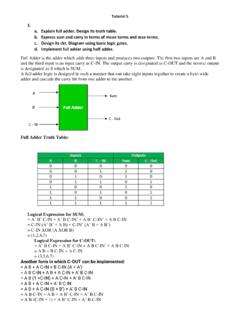
1. a. Explain full adder. Design its truth table. b ...
cvbl.iiita.ac.inImplementation of Full Adder using Half Adders 2 Half Adders and a OR gate is required to implement a Full Adder. 2. a. Explain full substractor. Design its truth table. b. Express sum and carry in terms of mean terms and max terms. c. Design its ckt. Diagram using basic logic gates. d. Implement full adder using half adder. Full Subtractor in ...

UNIT 3 COMBINATIONAL LOGIC
www.pvpsiddhartha.ac.inHence, by using full adders subtraction can be carried out. Figure above the realization of 4 bit adder-subtractor. From the figure it can be seen that, the bits of the binary numbers are given to full adder through the XOR gates. The control input …

1 LIST OF EXPERIMENTS
www.kctgroups.comFULL ADDER: A full adder is a combinational circuit that forms the arithmetic sum of input; it consists of three inputs and two outputs. A full adder is useful to add three bits at a time but a half adder cannot do so. In full adder sum output will be taken from X-OR Gate, carry output will be taken from OR Gate. HALF SUBTRACTOR:

Booth Multiplier Implementation of Booth’s Algorithm using ...
www.vlsiip.comproducts. Carry-Save-Adders are used to add the partial products. Results of tim-ing and area are then shown. The results table contain area and timing results of 3 multipliers i.e ordinary array multiplier, radix-4 booth’s multiplier (without CSA), and radix-4 booth’s multiplier with CSA. Results are then discussed. The