Transcription of OPA657 1.6-GHz, Low-Noise, FET-Input Operational Amplifier ...
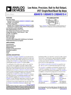
1 Frequency (Hz)11610696867666100k1M10M50 MTransimpedance Gain (dB)10 MHz BandwidthOPA657(12pF)l-Vb200k! &BuyTechnicalDocumentsTools &SoftwareSupport &CommunityOPA657 SBOS197F DECEMBER2001 , Low-Noise, FET-InputOperationalAmplifier 1 Features3 DescriptionThe OPA657devicecombinesa high-gainbandwidth,1 GHzlow-distortion,voltage-feedbackoperat ionalamplifier HighBandwidth275 MHz(G = 10)with a low-voltagenoiseJFET-inputstageto offera SlewRate700 V/ s (G = 10, 1-V Step)veryhighdynamicrangeamplifierfor high-precisionADC(analog-to-digitalconve rter)drivingor wideband Availablein OperatingTemperatureRange: 40 C to 85 Cdecompensated,high-gainbandwidthamplifi er. Low-InputOffsetVoltage: 250 VVerylow levelsignalscan be significantlyamplifiedin Low-InputBiasCurrent:2 pAa singleOPA657gainstagewithexceptional Low- nV/ Hzbandwidthand high High-OutputCurrent:70 mAbandwidthsup to gainsof 160 V/V (44 dB). The very FastOverdriveRecoverylow inputbiascurrentand capacitancesupportsthisperformanceevenfo rrelativelyhighsource2 Applicationsimpedances.
2 WidebandPhotodiodeAmplifierBroadbandphot odetectorapplicationsbenefitfrom WaferScanningEquipmentthe low-voltagenoiseJFET inputsfor the jfet inputcontributesvirtuallyno currentnoise ADCI nputAmplifierwhilefor broadbandapplications,a low voltagenoise Testand MeasurementFrontEndis nV/ Hz inputvoltage HighGainPrecisionAmplifiernoiseprovidese xceptionalinputsensitivityfor OpticalTimeDomainReflectometry(OTDR)give sa totalequivalentinputnoisecurrentof Hz overa (1)PARTNUMBERPACKAGEBODYSIZE(NOM)SOT-23( 5) (8) (1) For all availablepackages,see the orderableaddendumatthe end of the 200-k TransimpedanceWidebandPhotodiodeTransimp edanceAmplifierAmplifier1An IMPORTANTNOTICEat the end of this datasheetaddressesavailability,warranty, changes,use in safety-criticalapplications,intellectual propertymattersand DECEMBER2001 Applicationand Pin Configurationand Deviceand :VS= 5 :VS- 5 V, :VS= 5 Mechanical,Packaging,and Orderable8 RevisionHistoryNOTE:Pagenumbersfor previousrevisionsmay differfrompagenumbersin the (December2008)to RevisionFPage AddedESDR atingstable,FeatureDescriptionsection,De viceFunctionalModes,ApplicationandImplem entationsection,PowerSupplyRecommendatio nssection,Layoutsection,DeviceandDocumen tationSupportsection,andMechanical,Packa ging, AddedPowerSupply,MinimumOperatingVoltage specificationto (March2006)to RevisionEPage Changedminimumstoragetemperaturerangefro m 40 C to 65 C.
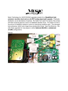
3 42 SubmitDocumentationFeedbackCopyright 2001 2015,TexasInstrumentsIncorporatedProduct FolderLinks:OPA65712354+VSVIN VOUT-VSVIN+A57154 Pin Orientation/Package Marking2312348765NC+VSVOUTNCNCVIN VIN+ DECEMBER2001 REVISEDAUGUST20155 RelatedOperationalAmplifierProductsSLEWR ATEVOLTAGENOISEDEVICEVS(V)BW (MHz)(V/ s)(nV/ Hz)AMPLIFIERDESCRIPTIONOPA657 +7 stableFET InputOPA656 52302907 Unity-GainStableFET-InputOPA659 +10 stableBipolarInputTHS4631 1521010007 Unity-GainStableFET-InputProgrammableGai n(5 k / 20 k )OPA85754750220 TransimpedanceAmplifier6 Pin Configurationand FunctionsD PackageDBVP ackage8-PinSOICS urface-Mount5-PinSOT-23 Top ViewTop ViewPin FunctionsPINI/ODESCRIPTIONNAMESOICSOT-23 1NC5 No Connection8 VIN 24 IInvertingInputVIN+33 INoninvertingInput VS42 POWN egativePowerSupplyVOUT61 OOutputof Amplifier +VS75 POWP ositivePowerSupplyCopyright 2001 2015,TexasInstrumentsIncorporatedSubmitD ocumentationFeedback3 ProductFolderLinks: OPA657 OPA657 SBOS197F DECEMBER2001 (unlessotherwisenoted)(1)MINMAXUNITS upplyvoltage(TotalBipolarSupplies) VS+VSVI nputvoltage VS+VSVJ unctiontemperature(TJ)175 CStoragetemperature 65125 C(1)StressesbeyondthoselistedunderAbsolu teMaximumRatingsmay causepermanentdamageto the stressratingsonly,whichdo not implyfunctionaloperationof the deviceat theseor any otherconditionsbeyondthoseindicatedunder RecommendedOperatingConditions.
4 Exposureto absolute-maximum-ratedconditionsfor extendedperiodsmay (HBM),per ANSI/ESDA/JEDECJS-001(1) 2000 Charged-devicemodel(CDM),per JEDEC specificationJESD22-V(ESD)Electrostaticd ischarge 500VC101(2)MachineModel(MM) 200(1)JEDEC documentJEP155statesthat 500-VHBM allowssafe manufacturingwith a standardESDcontrolprocess.(2)JEDEC documentJEP157statesthat 250-VCDM allowssafe manufacturingwith a (unlessotherwisenoted)MINNOMMAXUNITVST otalsupplyvoltage81012 VTAA mbienttemperature 402585 (1)D (SOIC)DBV(SOT-23)UNIT8 PINS5 PINSR JAJunction-to-ambientthermalresistance12 5150 C/WR JC(top)Junction-to-case(top) C/WR C/W C/W C/WR JC(bot)Junction-to-case(bottom)thermalre sistance C/W(1)For moreinformationabouttraditionaland new thermalmetrics,see theSemiconductorandICPackageThermalMetri csapplicationreport, 2001 2015, DECEMBER2001 :VS= 5 VAt RF= +453 , RL= +100 , and G = +10 V/V, Figure29 for AC (1)AC PERFORMANCE(seeFigure29)G = +7 V/V, VO= 200 mVPPTJ= 25 C350 Small-signalbandwidthG = +10 V/V, VO= 200 mVPPTJ= 25 C275 MHzCG = +20 V/V, VO= 200 mVPPTJ= 25 C90 Gain-bandwidthproductG > +40 V/VTJ= 25 C1600dBCBandwidthfor = +10 V/V, 2 VPPTJ= 25 C30 MHzCPeakingat a Gainof +7TJ= 25 C7dBCLarge-SignalBandwidthG = +10 V/V, 2 VPPTJ= 25 C180 MHzCSlewRateG = +10 V/V, 1-V StepTJ= 25 C700V/ 25 C1nsCSettlingTimeto = +10 V/V, VO= 2-V StepTJ= 25 C20nsCHarmonicDistortionG = +10 V/V, f = 5 MHz,VO= 2 VPPCRL= 200 TJ= 25 C 70dBcC2nd-HarmonicRL> 500 TJ= 25 C 74dBcCRL= 200 TJ= 25 C 99dBcC3rd-HarmonicRL> 500 TJ= 25 C 106dBcCInputVoltageNoisef > 100 kHzTJ= 25 HzCInputCurrentNoisef > 100 kHzTJ= 25 HzCDC PERFORMANCE(2)TJ= 25 C6570 Open-LoopVoltageGain(AOL)VCM= 0 V, RL= 100 TJ= 0 C to 70 C(3)64dBATJ= 40 C to 85 C(3)63TJ= 25 C 0 VTJ= 0 C to 70 C(3) 40 C to 85 C(3)
5 25 C 12 2 AverageOffsetVoltageDriftVCM= 0 VTJ= 0 C to 70 C(3) 12 V/ CATJ= 40 C to 85 C(3) 12TJ= 25 C 2 20 InputBiasCurrentVCM= 0 VTJ= 0 C to 70 C(3) 1800pAATJ= 40 C to 85 C(3) 5000TJ= 25 C 1 10 InputOffsetCurrentVCM= 0 VTJ= 0 C to 70 C(3) 900pAATJ= 40 C to 85 C(3) 2500 INPUTTJ= 25 (4)TJ= 0 C to 70 C(3) 40 C to 85 C(3) 25 C 4 MostNegativeInputVoltage(4)TJ= 0 C to 70 C(3) 40 C to 85 C(3) 25 C8389 Common-ModeRejectionRatio(CMRR)VCM= VTJ= 0 C to 70 C(3)81dBATJ= 40 C to 85 C(3)79 InputImpendance(1)TestLevels:(A) 100%testedat +25 C. Over-temperaturelimitsby characterizationand simulation.(B) Limitsset by characterizationand simulation.(C) Typicalvalueonly for information.(2)Currentis the inputcommon-modevoltage.(3)Junctiontempe rature= ambientat low temperaturelimit:junctiontemperature= ambient+20 C at high temperaturelimit for overtemperaturespecifications.(4)Tested< 3dB belowminimumspecifiedCMRRat 2001 2015,TexasInstrumentsIncorporatedSubmitD ocumentationFeedback5 ProductFolderLinks: OPA657 OPA657 SBOS197F DECEMBER2001.
6 VS= 5 V (continued)At RF= +453 , RL= +100 , and G = +10 V/V, Figure29 for AC (1)DifferentialTJ= 25 C || pFC1012|| 25 C || pFC1012|| 25 C loadVATJ= 0 C to 70 C(3) 25 C 100 TJ= 0 C to 70 C(3) 40 C to 85 C(3) 25 C5070 CurrentOutput,SourcingTJ= 0 C to 70 C(3)48mAATJ= 40 C to 85 C(3)46TJ= 25 C 50 70 CurrentOutput,SinkingTJ= 0 C to 70 C(3) 48mAATJ= 40 C to 85 C(3) 46 Closed-LoopOutputImpedanceG = +10 V/V, f = MHzTJ= 25 APOWERSUPPLYS pecifiedOperatingVoltageTJ= 25 C 5 VAMinimumOperatingVoltageTJ= 25 C 4 VCTJ= 25 C 6 MaximumOperatingVoltageRangeTJ= 0 C to 70 C(3) 6 VATJ= 40 C to 85 C(3) 6TJ= 25 C1416 MaximumQuiescentCurrentTJ= 0 C to 70 C(3) 40 C to 85 C(3) 25 0 C to 70 C(3) 40 C to 85 C(3) 25 C7680 Power-SupplyRejectionRatio(+PSRR)+VS = V to VTJ= 0 C to 70 C(3)74dBATJ= 40 C to 85 C(3)72TJ= 25 C6268 Power-SupplyRejectionRatio( PSRR) VS = V to VTJ= 0 C to 70 C(3)60dBATJ= 40 C to 85 C(3)58 TEMPERATURERANGES pecifiedOperatingRange:U, NTJ= 25 C 40 to +85 CPackageThermalResistance,R JAJunction-to-AmbientU: SO-8TJ= 25 C125 C/WN: SOT23-5TJ= 25 C150 C/W6 SubmitDocumentationFeedbackCopyright 2001 2015, DECEMBER2001 :VS- 5 V, High-GradeDC SpecificationsAt RF= 453 , RL= 100 , and G = +10 V/V, unlessotherwisenoted.
7 (1)TESTPARAMETERTESTCONDITIONSMINTYPMAXU NITLEVEL(2)TJ= 25 C (3)InputOffsetVoltageVCM= 0 VTJ= 0 C to 70 C(4) 40 C to 85 C(4) 25 C 2 6(3)InputOffsetVoltageDriftVCM= 0 VTJ= 0 C to 70 C(4) 6 V/ CATJ= 40 C to 85 C(4) 6TJ= 25 C 1 5(3)InputBiasCurrentVCM= 0 VTJ= 0 C to 70 C(4) 450pAATJ= 40 C to 85 C(4) 1250TJ= 25 C 5(3)InputOffsetCurrentVCM= 0 VTJ= 0 C to 70 C(4) 450pAATJ= 40 C to 85 C(4) 1250TJ= 25 C91(3)98 Common-ModeRejectionVCM= VTJ= 0 C to 70 C(4)89dBARatio(CMRR)TJ= 40 C to 85 C(4)87TJ= 25 C78(3)82 Power-SupplyRejection+VS= V to VTJ= 0 C to 70 C(4)76dBARatio(+PSRR)TJ= 40 C to 85 C(4)74TJ= 25 C68(3)74 Power-SupplyRejection VS= V to VTJ= 0 C to 70 C(4)66dBARatio( PSRR)TJ= 40 C to 85 C(4)64(1)All otherspecificationsare the sameas the standard-grade.(2)TestLevels:(A) 100%testedat +25 C. Overtemperaturelimitsby characterizationand simulation.(3)Junctiontemperature= ambientfor +25 C specifications.(4)Junctiontemperature= ambientat low temperaturelimit:junctiontemperature= ambient+20 C at high temperaturelimit for 2001 2015,TexasInstrumentsIncorporatedSubmitD ocumentationFeedback7 ProductFolderLinks.
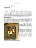
8 OPA657 Time (10ns/div)Small-Signal Output Voltage (200mV/div)Large-Signal Output Voltage (400mV/div) Right ScaleSmall-Signal Left ScaleSee Figure 28G = +10 Time (10ns/div)Small-Signal Output Voltage (200mV/div)Large-Signal Output Voltage (400mV/div) Right ScaleSmall-Signal Left ScaleSee Figure 29G = (MHz)Gain (dB)262320171411852-1-4 See Figure 28G = +10V = 5 VOPPV = 2 VOPPV = 1 VOPPV = (MHz)Gain (dB)3229262320171411852 See Figure 29G = 20-R = 1kWFV = 5 VOPPV = 1 VOPPV = 1 VOPPV = (MHz)Normalized Gain (dB)9630-3-6-9-12-15-18-21 See Figure 28G = +20G = +50G = +10V = = + (MHz)Normalized Gain (dB)9630-3-6-9-12-15-18-21 See Figure 29V = = 50 GWG = 12-G = 20-G = 50- OPA657 SBOS197F DECEMBER2001 :VS= 5 VAt TA= 25 C, G = 10 V/V, RF= 453 , and RL= 100 , NoninvertingSmall-SignalFrequencyRespons eFigure2. InvertingSmall-SignalFrequencyResponseFi gure3. NoninvertingLarge-SignalFrequencyRespons eFigure4. InvertingLarge-SignalFrequencyResponseFi gure5.
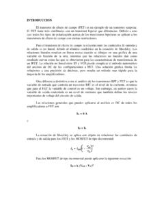
9 NoninvertingPulseResponseFigure6. InvertingPulseResponse8 SubmitDocumentationFeedbackCopyright 2001 2015,TexasInstrumentsIncorporatedProduct FolderLinks:OPA65751050 Gain (V/V)Harmonic Distortion (dBc)-40-50-60-70-80-90-100-110V = 2 VOPPf = 5 MHzR = 200WL2nd Harmonic3rd HarmonicSee Figure 28, R AdjustedG1050 Gain (V/V)Harmonic Distortion (dBc)-40-50-60-70-80-90-100-110V = 2 VOPPR = 50 WGf = 5 MHzR = 200 WLSee Figure 29, R AdjustedF2nd Harmonic3rd Voltage Swing (V )PPHarmonic Distortion (dBc)-70-75-80-85-90-95-100-105-110f = 1 MHzR = 200 WLSee Figure 282nd Harmonic3rd (MHz)Harmonic Distortion (dBc)-50-60-70-80-90-100-1103rd Harmonic2nd HarmonicV = 2 VOPPR = 200 WLSee Figure Voltage Swing (V )PPHarmonic Distortion (dBc)-60-65-70-75-80-85-90-95-100-105f = 5 MHzR = 200WL2nd Harmonic3rd HarmonicSee Figure 281001kResistance ( )WHarmonic Distortion (dBc)-60-65-70-75-80-85-90-95-100-105-11 0V = 2 VOPPf = 5 MHzSee Figure 282nd Harmonic3rd DECEMBER2001 REVISEDAUGUST2015 TypicalCharacteristics.
10 VS= 5 V (continued)At TA= 25 C, G = 10 V/V, RF= 453 , and RL= 100 , HarmonicDistortionvs LoadResistanceFigure8. HarmonicDistortionvs OutputVoltage(5 MHz)Figure9. HarmonicDistortionvs FrequencyFigure10. HarmonicDistortionvs OutputVoltage(1 MHz)Figure11. HarmonicDistortionvs NoninvertingGainFigure12. HarmonicDistortionvs InvertingGainCopyright 2001 2015,TexasInstrumentsIncorporatedSubmitD ocumentationFeedback9 ProductFolderLinks:OPA657101001kCapaciti ve Load (pF)R (SW)100101 For Maximally-Flat Frequency Response110100500 Frequency (MHz)Normalized Gain to Capacitive Load (dB)2320171411852RS50W1kWVIVOCL50W453 WOPA657C = 22pFLC = 100pFLC = 10pFL1k100k1M10M10k100 MFrequency (Hz)CMRR, PSRR (dB)1101009080706050403020 CMRR+PSRR-PSRR 270 225 180 135 90 45045 40 20020406080100 Open Loop Gain - Phase ( ) Open Loop Gain - Magnitude (dB)Frequency (Hz)Aol MagnitudeAol PhaseD00120log10(AOL) AOL1001k10k 100k1M10M 100M1G-10-8-6-4-242068 Single-ower (dBm)Tone Load P3rd-Order Spurious Level (dBc)-50-60-70-80-90-1005 MHz15 MHz20 MHz10 MHz50W50W50 WPIPO50W453 WOPA657101001k10k100k1M10 MFrequency (Hz)e (nV/n ), i (fA/n )HzHz100101 Input Voltage Noise HzInput Current Noise HzOPA657 SBOS197F DECEMBER2001.