Transcription of PCF8575 Remote16-BIT I2C AND SMBus I/O Expander with ...
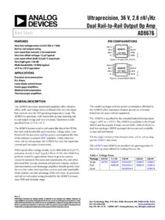
1 PCF8575I2C or SMBus Master( Processor)Peripheral Devices RESET, ENABLE, orcontrol inputs INT or statusoutputs LEDsSDASCLINTA0A1A2 GNDVCCP00P01P02P03P04P05P06P07 Peripheral DevicesRESET, ENABLE, orcontrol inputsINT or statusoutputsLEDsP10P11P12P13P14P15P16P1 7 ProductFolderOrderNowTechnicalDocumentsT ools &SoftwareSupport &CommunityAn IMPORTANTNOTICEat the end of this datasheetaddressesavailability,warranty, changes,use in safety-criticalapplications,intellectual propertymattersand JANUARY2005 REVISEDAUGUST2018 PCF8575 Remote16-BITI2C AND SMBusI/O Expanderwith InterruptOutput11 Features1 I2C to Parallel-PortExpander Open-DrainInterruptOutput Low Standby-CurrentConsumptionof 10 A Max CompatibleWithMostMicrocontrollers 400-kHzFastI2C Bus Addressby ThreeHardwareAddressPinsfor Useof up to EightDevices LatchedOutputsWithHigh-CurrentDriveCapab ilityfor DirectlyDrivingLEDs CurrentSourceto VCCfor ActivelyDrivinga Highat the output Latch-UpPerformanceExceeds100 mA PerJESD78.
2 ClassII ESDP rotectionExceedsJESD22 2000-VHuman-BodyModel 200-VMachineModel 1000-VCharged-DeviceModel2 Applications TelecomShelters:FilterUnits Servers Routers(TelecomSwitchingEquipment) PersonalComputers PersonalElectronics IndustrialAutomation Productswith GPIO-LimitedProcessors3 DescriptionThis16-bitI/O expanderfor the two-linebidirectionalbus(I2C) is designedfor mostmicrocontrollerfamiliesby wayof the I2C interface[serialclock(SCL),serialdata(SD A)].Thedevicefeaturesa 16-bitquasi-bidirectionalinput/ output (I/ O)port (P07 P00,P17 P10), canbe usedas an inputor outputwithoutthe use of poweron, the I/Osare this mode,only a currentsourceto (1)PARTNUMBERPACKAGE(PIN)BODYSIZE(NOM)PC F8575 SSOP(24) (24) (24) (24) (24) (24) (1) For all availablepackages,see the orderableaddendumatthe end of the JANUARY2005 : PCF8575 SubmitDocumentationFeedbackCopyright 2005 2018,TexasInstrumentsIncorporatedTableof Contents1 Pin Configurationand Applicationand Deviceand Mechanical,Packaging,and RevisionHistoryChangesfromRevisionF (May2015)to RevisionGPage (January2015)to RevisionFPage Fixednamingtypo in the RGEgraphic,changedpin 3 From:P03 To: P02.
3 3 ChangesfromRevisionD (April2007)to RevisionEPage AddedApplications,DeviceInformationtable ,PinFunctionstable,ESDR atingstable,ThermalInformationtable,Typi calCharacteristics,FeatureDescriptionsec tion,DeviceFunctionalModes,Applicationan dImplementationsection,PowerSupplyRecomm endationssection,Layoutsection,Deviceand DocumentationSupportsection,andMechanica l,Packaging, VCC 2A123 SDA3A222 SCL4P0021 A05P0120 P176P0219 P167P0318 P158P0417 P149P0516 P1310P0615 P1211P0714 P1112 GND13 P10 Not to scale24A27P061P0018 A023A18P072P0117 P1722 INT9 GND3P0216 P1621 VCC 10P104P0315 P1520 SDA11P115P0414 P1419 SCL12P126P0513 P13 Not to JANUARY2005 REVISEDAUGUST2018 ProductFolderLinks: PCF8575 SubmitDocumentationFeedbackCopyright 2005 2018,TexasInstrumentsIncorporated5 Pin Configurationand FunctionsDB, DBQ,DGV,DW,or PW PackageSSOP,TVSOP,SOIC,TSSOP(TopView)RGE P ackageVQFN(TopView)Pin FunctionsPINTYPEDESCRIPTIONNAMEDB, DBQ,DGV,DW,ANDPWRGEA02118 IAddressinput0. Connectdirectlyto VCCor not Connectdirectlyto VCCor not Connectdirectlyto VCCor not VCCthrougha GroundP101310I/OP- Connectto VCCthrougha pull-upresistorSDA2320I/OSerialdataline.
4 Connectto VCCthrougha Supplyvoltage4 PCF8575 SCPS121G JANUARY2005 : PCF8575 SubmitDocumentationFeedbackCopyright 2005 2018,TexasInstrumentsIncorporated(1)Stre ssesbeyondthoselistedunderAbsoluteMaximu mRatingsmay causepermanentdamageto the stressratingsonly,and functionaloperationof the deviceat theseor any otherconditionsbeyondthoseindicatedunder RecommendedOperatingConditionsis not absolute-maximum-ratedconditionsfor extendedperiodsmay affectdevicereliability.(2)The inputnegative-voltageand outputvoltageratingsmay be exceededif the inputand outputcurrentratingsare (unlessotherwisenoted)(1)MINMAXUNITVCCS upplyvoltagerange (2) + (2) + < 0 20mAIOKO utputclampcurrentVO< 0 20mAIOKI nput/outputclampcurrentVO< 0 or VO> VCC 20mAIOLC ontinuousoutputlow currentVO= 0 to VCC50mAIOHC ontinuousoutputhigh currentVO= 0 to VCC 4mAContinuouscurrentthroughVCCor GND 100mATstgStoragetemperaturerange150 (ESD)ElectrostaticdischargeHumanbodymode l(HBM),per ANSI/ESDA/JEDECJS-001,all pins2000 VChargeddevicemodel(CDM),per JEDEC specificationJESD22-C101,all VCCVCC+ VCCVIOHP-porthigh-leveloutputcurrent 1mAIOHTP-porttransientpullupcurrent 10mAIOLP-portlow-leveloutputcurrent25mAT AO peratingfree-airtemperature 4085 C(1)For moreinformationabouttraditionaland new thermalmetrics,see (1) PCF8575 UNITDBDBQDGVDWPWRGE24 PINSR JAJunction-to-ambientthermalresistance63 6186468853 JANUARY2005 REVISEDAUGUST2018 ProductFolderLinks.
5 PCF8575 SubmitDocumentationFeedbackCopyright 2005 2018,TexasInstrumentsIncorporated(1)All typicalvaluesare at nominalsupplyvoltage( , ,or 5-V VCC) and TA= 25 C.(2)The power-onresetcircuitresetsthe I2C bus logicwith VCC< VPORand sets all I/Os to logichigh (withcurrentsourceto VCC). (unlessotherwisenoted)PARAMETERTESTCONDI TIONSVCCMINTYP(1)MAXUNITVIKI nputdiodeclampvoltageII= 18 V to V (2)VI= VCCor GND,IO= portVO= V to V 30 300 AIOHTP-porttransientpullupcurrentHighdur ingACK,VOH= V 1mAIOLSDAVOL= V to V3mAP portVOL= V515 VOL= 1 V1025 INTVOL= ,SDAVI= VCCor V to V 5 AA0, A1, A2 1 IIHLP portVI VCCor VI V to V 400 AICCO peratingmodeVI= VCCor GND,IO= 0,fscl= 400 V100200 V2050 StandbymodeVI= VCCor GND,IO= 0, fscl= 0 ICCS upplycurrentincreaseOne inputat VCC V,Otherinputsat VCCor V to V200 ACISCLVI= VCCor V to V37pFCioSDAVIO= VCCor V to V37pFP port410(1)Cb= total bus capacitanceof one bus line in InterfaceTimingRequirementsoverrecommend edoperatingfree-airtemperaturerange(unle ssotherwisenoted)(seeFigure12)MINMAXUNIT fsclI2C clockfrequency400kHztschI2C clockhigh stsclI2C clocklow stspI2C spiketime50nstsdsI2C serialdatasetuptime100nstsdhI2C serialdatahold time0nsticrI2C inputrise time20 + (1)
6 300nsticfI2C inputfall time20 + (1)300nstocfI2C outputfall time10-pFto 400-pFbus300nstbufI2C bus free time betweenStopand ststsI2C startor ststhI2C startor stspsI2C stvdValid-datatimeSCLlow to sCbI2C bus Current ( A)mfSCL= 100 kHzAll I/Os unloadedSupply Voltage (V) VTA= 40 CTA= 25 CTA= 85 CISINK(mA)Vol (V)0102030405060708090 50 25 025 50 75 100 125 Temperature ( C)Supply Current ( A)mSCL = VCCAll I/Os unloadedVCC= 5 VVCC= VVCC= V020406080100120 50 250255075 100 125 Temperature ( C)Supply Current ( A)mfSCL= 100 kHzAll I/Os unloadedVCC= 5 VVCC= VVCC= V6 PCF8575 SCPS121G JANUARY2005 : PCF8575 SubmitDocumentationFeedbackCopyright 2005 2018, ,CL 100 pF (unlessotherwisenoted)(seeFigure13 and Figure14)PARAMETERFROM(INPUT)TO( output )M INMAXUNITtivInterruptvalidtimeP portINT4 stirInterruptresetdelaytimeSCLINT4 stpvOutputdatavalidSCLP port4 stsuInputdatasetuptimeP portSCL0 sthInputdatahold timeP portSCL4 25 C (unlessotherwisenoted)Figure1.
7 SupplyCurrentvs TemperatureFigure2. StandbySupplyCurrentvs TemperatureFigure3. SupplyCurrentvs SupplyVoltageFigure4. I/O SinkCurrentvs VTA= 40 CTA= 25 CTA= 85 CVCC VOH(V)ISOURCE(mA) 5 VTA= 40 CTA= 85 CTA= 25 CVCC VOH(V)ISOURCE(mA)0100200300400500600 50 25 025 50 75 100 125 Temperature ( C)VCC= 5 V, ISINK= 10 mAVCC= V, ISINK= 10 mAVCC= 5 V,ISINK= 1 mAVCC= V,ISINK= 1mAVOL(mV) VTA= 40 CTA= 25 CTA= 85 CVCC VOH(V)ISOURCE(mA) VTA= 25 CTA= 85 CTA= 40 CVOL(V)ISINK(mA) 5 VTA= 40 CTA= 25 CTA= 85 CVOL(V)ISINK(mA) JANUARY2005 REVISEDAUGUST2018 ProductFolderLinks: PCF8575 SubmitDocumentationFeedbackCopyright 2005 2018,TexasInstrumentsIncorporatedTypical Characteristics(continued)TA= 25 C (unlessotherwisenoted)Figure5. I/O SinkCurrentvs OutputLowVoltageFigure6. I/O SinkCurrentvs OutputLowVoltageFigure7. I/O OutputLowVoltagevs TemperatureFigure8. I/O SourceCurrentvs OutputHighVoltageFigure9.
8 I/O SourceCurrentvs OutputHighVoltageFigure10. I/O SourceCurrentvs OutputHighVoltage050100150200250300350 50 25 025 50 75 100 125 Temperature ( C)VCC= 5 VVCC VOH(V)VCC= VVCC= V8 PCF8575 SCPS121G JANUARY2005 : PCF8575 SubmitDocumentationFeedbackCopyright 2005 2018,TexasInstrumentsIncorporatedTypical Characteristics(continued)TA= 25 C (unlessotherwisenoted)Figure11. I/O HighVoltagevs TemperatureRL= 1 kWVCCCL= 50 VCCStopConditiontspsRepeatStartCondition Start orRepeatStartConditionSCLSDAS tartCondition(S)AddressBit 7(MSB)DataBit 10(LSB)StopCondition(P)3 Bytes for Complete DeviceProgrammingSDA LOAD CONFIGURATIONVOLTAGE WAVEFORMS ticfStopCondition(P) VCCR/WBit 0(LSB)ACK(A)DataBit 07(MSB)AddressBit 1 AddressBit 6 BYTEDESCRIPTION12, 3I2C addressP-port JANUARY2005 REVISEDAUGUST2018 ProductFolderLinks: PCF8575 SubmitDocumentationFeedbackCopyright 2005 2018,TexasInstrumentsIncorporated7 ParameterMeasurementInformationFigure12. I2C InterfaceLoadCircuitand VoltageWaveformsAAAAS0100A1A2A01 data 11 PData 3 StartCondition16 Bits(2 data Bytes)From PortData From PortSlave Address ( PCF8575 )R/W87654321tirtirtspstivAddress data 1 data 3 VCCINTSCLView B BView A AtivRL= k VCCCL= 100 pFINTERRUPT LOAD CONFIGURATIONDUTINTACKFrom SlaveACKFrom SlaveData 2 data 210 PCF8575 SCPS121G JANUARY2005 : PCF8575 SubmitDocumentationFeedbackCopyright 2005 2018,TexasInstrumentsIncorporatedParamet erMeasurementInformation(continued)Figur e13.
9 InterruptLoadCircuitand VCCSCLP17tpvSlaveACKU nstableDataLast Stable BitSDAPnPnWrite-Mode Timing (R/W= 0) VCCtsuthRead-Mode Timing (R/W= 1)DUTGNDCL= 100 pFRL= k VCCSDA LOAD CONFIGURATIONINTERRUPT LOAD CONFIGURATIONINTGNDCL= 50 pFRL= 1 k VCCDUTSDADUTGNDCL= 100 pFP-PORT LOAD JANUARY2005 REVISEDAUGUST2018 ProductFolderLinks: PCF8575 SubmitDocumentationFeedbackCopyright 2005 2018,TexasInstrumentsIncorporatedParamet erMeasurementInformation(continued)Figur e14. P-PortLoadCircuitsand VoltageWaveforms12 PCF8575 SCPS121G JANUARY2005 : PCF8575 SubmitDocumentationFeedbackCopyright 2005 2018,TexasInstrumentsIncorporated8 expansionfor mostmicrocontrollerfamiliesvia the I2 Cinterfaceserialclock(SCL)and serialdata(SDA).The devicefeaturesa 16-bitquasi-bidirectionalinput/ output (I/ O)port (P07 P00,P17 P10),includinglatchedoutputswith high-currentdrivecapabilityfor can be usedas aninputor outputwithoutthe use of a poweron, the I/Os are this mode,only a currentsource(IOH) to VCCis additionalstrongpullupto VCC(IOHT) whenan outputis writtenhighand is switchedoff by the negativeedgeof I/Os shouldbe highbeforebeingusedas , as all the I/Os are set high,all of themcan be usedas changein settingof the I/Os as eitherinputor outputscan be donewiththe a highis appliedexternallyto an I/O that has beenwrittenearlierto low, a largecurrent(IOL)will flow to PCF8575providesan open-draininterrupt(INT)
10 output ,whichcan be connectedto the interruptinputof interruptis generatedby any risingor fallingedgeof the port inputsin the ,tiv, the signalINT is reactivatingthe interruptcircuitis achievedwhendataon the portis changedto the originalsetting,or datais readfromor writtento the port that generatedthe the readmodeat the acknowledge(ACK)bit afterthe risingedgeof the SCLsignalor in the writemodeat the ACKbit afterthe fallingedgeof the occurduringthe ACKclockpulsecanbe lost (or be veryshort),due to the resettingof the interruptduringthis the I/Osafterresettingis detectedand is transmittedas writingto anotherdevicedoesnot haveinternalconfigurationor ,reador writeto thedeviceI/Os directlyaftersendingthe deviceaddress(seeFigure18 and Figure19).By sendingan interruptsignalon this line, the remoteI/O can informthe microcontrollerif thereis incomingdataon its ports,withouthavingto communicatevia the I2C ,the PCF8575can remaina or fromthe PCF8575mustconsistof an evennumberof first databyte ineverypair refersto port 0 (P07 P00),and the seconddatabyte in everypair refersto port 1 (P17 P10).