Transcription of PIC12(L)F1571/2 Data Sheet - Microchip Technology
1 2013-2015 Microchip Technology 1 PIC12(L)F1571/2 Description: PIC12(L)F1571/2 microcontrollers combine the capabilities of 16-bit PWMs with Analog to suit a variety of devices deliver three 16-bit PWMs with independent timers for applications where high resolution is needed, suchas LED lighting, stepper motors, power supplies and other general purpose applications. The core independentperipherals (16-bit PWMs, Complementary Waveform Generator), Enhanced Universal Synchronous AsynchronousReceiver transceiver (EUSART) and Analog (ADCs, Comparator and DAC) enable closed-loop feedback andcommunication for use in multiple market segments. The EUSART peripheral enables the communication forapplications such as Features: C Compiler Optimized RISC Architecture Only 49 Instructions Operating Speed:- DC 32 MHz clock input- 125 ns minimum instruction cycle Interrupt Capability 16-Level Deep Hardware Stack Two 8-Bit Timers One 16-Bit Timer Three Additional 16-Bit Timers available using the 16-Bit PWMs Power-on Reset (POR) Power-up Timer (PWRT) Low-Power Brown-out Reset (LPBOR) Programmable Watchdog Timer (WDT) up to 256s Programmable Code ProtectionMemory: Up to Kbytes Flash Program Memory Up to 256 Bytes data SRAM Memory Direct, Indirect and Relative Addressing modes High-Endurance Flash data Memory (HEF)- 128 bytes if nonvolatile data storage- 100k erase/write cyclesOperating Characteristics: Operating Voltage Range.
2 - to (PIC12LF1571/2)- to (PIC12F1571/2) Temperature Range:- Industrial: -40 C to +85 C- Extended: -40 C to +125 C Internal Voltage Reference module In-Circuit Serial Programming (ICSP ) via Two PinseXtreme Low-Power (XLP) Features: Sleep mode: 20 nA @ , Typical Watchdog Timer: 260 nA @ , Typical Operating Current:-30 A/MHz @ , typicalDigital Peripherals: 16-Bit PWM:- Three 16-bit PWMs with independent timers- Multiple Output modes (Edge-Aligned, Center-Aligned, Set and Toggle on Register Match)- User settings for phase, duty cycle, period, offset and polarity- 16-bit timer capability- Interrupts generated based on timer matches with Offset, Duty Cycle, Period and Phase registers Complementary Waveform Generator (CWG):- Rising and falling edge dead-band control- Multiple signal sources Enhanced Universal Synchronous Asynchronous Receiver transceiver (EUSART):- Supports LIN applicationsDevice I/O Port Features: Six I/Os Individually Selectable Weak Pull-ups Interrupt-On-Change Pins Option with Edge-Selectable Option8-Pin MCU with High-Precision 16-Bit PWMsPIC12(L) f1571 /2DS40001723D-page 2 2013-2015 Microchip Technology Peripherals: 10-Bit Analog-to-Digital Converter (ADC):- Up to four external channels- Conversion available during Sleep Comparator:- Low-Power/High-Speed modes - Fixed Voltage Reference at (non)inverting input(s) - Comparator outputs externally accessible- Synchronization with Timer1 clock source - Software hysteresis enable 5-Bit Digital-to-Analog Converter (DAC).
3 - 5-bit resolution, rail-to-rail- Positive reference selection - Unbuffered I/O pin output - Internal connections to ADCs and comparators Voltage Reference: - Fixed voltage reference with , and output levelsClocking Structure: Precision Internal Oscillator:- Factory calibrated 1%, typical- Software-selectable clock speeds from 31 kHz to 32 MHz External Oscillator Block with:- Resonator modes up to 20 MHz- Two External Clock modes up to 32 MHz Fail-Safe Clock Monitor Digital Oscillator Input AvailablePIC12(L) f1571 /2 FAMILY TYPESD eviceData Sheet IndexProgram Memory Flash(K words) data SRAM (bytes)High-EnduranceFlash (bytes)I/O Pins8-Bit/16-Bit Timers Comparators16-Bit PWM10-Bit ADC (ch)5-Bit DACCWGEUSARTD ebug(1)XLPPIC12(L)F1571A112812862/4(2)13 4110 I YPIC12(L)F1572A225612862/4(2)134111 IYNote 1:I Debugging integrated on :Three additional 16-bit timers available when not using the 16-bit PWM Sheet Index: (Unshaded devices are described in this document.)
4 ADS40001723 PIC12(L)F1571/2 data Sheet , 8-Pin Flash, 8-Bit MCU with High-Precision 16-Bit PWM. 2013-2015 Microchip Technology 3 PIC12(L)F1571/2 PIN DIAGRAMSPin Diagram 8-Pin PDIP, SOIC, DFN, MSOP, UDFN Note:See Ta b l e 1 for location of all peripheral (L) f1571 pic12 (L)F1572 TABLE 1:8-PIN ALLOCATION TABLE ( PIC12(L)F1571/2 )I/O8-Pin PDIP/SOIC/MSOP/DFN/UDFNADCR eferenceComparatorTimersPWMEUSART(2)CWGI nterruptPull-upBasicRA07AN0 DAC1 OUTC1IN+ PWM2TX(2)CK(2)CWG1 BIOCYICSPDATICDDATRA16AN1 VREF+C1IN0- PWM1RX(2)DT(2) IOCYICSPCLKICDCLKRA25AN2 C1 OUTT0 CKIPWM3 CWG1 FLTCWG1 AIOCINTY RA34 T1G(1) IOCYMCLRVPPRA43AN3 C1IN1-T1 GPWM2(1)TX(1,2)CK(1,2)CWG1B(1)IOCYCLKOUT RA52 T1 CKIPWM1(1)RX(1,2)DT(1,2)CWG1A(1)IOCYCLKI NVDD1 VDDVss8 VSSNote 1:Alternate pin function selected with the APFCON (Register 11-1) : pic12 (L)F1572 (L) f1571 /2DS40001723D-page 4 2013-2015 Microchip Technology of Overview.
5 Mid-Range CPU .. Organization .. Configuration .. Mode (Sleep) .. Timer (WDT) .. Flash Program Memory Control .. I/O Ports .. Interrupt-On-Change .. Fixed Voltage Reference (FVR) .. Temperature Indicator Module .. Analog-to-Digital Converter (ADC) Module .. 5-Bit Digital-to-Analog Converter (DAC) Module .. Comparator Timer0 Module .. Timer1 Module with Gate Timer2 Module .. Enhanced Universal Synchronous Asynchronous Receiver Transmitter (EUSART) .. 16-Bit Pulse-Width Modulation (PWM) Module .. Complementary Waveform Generator (CWG) Module .. In-Circuit Serial Programming (ICSP ) .. Instruction Set Summary .. Electrical DC and AC Characteristics Graphs and Charts .. Development Packaging 309 Appendix A: data Sheet Revision History .. 327 The Microchip Web Site .. 329 Customer Change Notification Service.
6 329 Customer Support .. 329 Product Identification 331 2013-2015 Microchip Technology 5 pic12 (L) f1571 /2TO OUR VALUED CUSTOMERSIt is our intention to provide our valued customers with the best documentation possible to ensure successful use of your Microchipproducts. To this end, we will continue to improve our publications to better suit your needs. Our publications will be refined andenhanced as new volumes and updates are introduced. If you have any questions or comments regarding this publication, please contact the Marketing Communications Department viaE-mail at We welcome your Current data SheetTo obtain the most up-to-date version of this data Sheet , please register at our Worldwide Web site at: can determine the version of a data Sheet by examining its literature number found on the bottom outside corner of any last character of the literature number is the version number, ( , DS30000000A is version A of document DS30000000).
7 ErrataAn errata Sheet , describing minor operational differences from the data Sheet and recommended workarounds, may exist for currentdevices. As device/documentation issues become known to us, we will publish an errata Sheet . The errata will specify the revisionof silicon and revision of document to which it determine if an errata Sheet exists for a particular device, please check with one of the following: Microchip s Worldwide Web site; Your local Microchip sales office (see last page)When contacting a sales office, please specify which device, revision of silicon and data Sheet (include literature number) you Notification SystemRegister on our web site at to receive the most current information on all of our (L) f1571 /2DS40001723D-page 6 2013-2015 Microchip Technology : 2013-2015 Microchip Technology 7 pic12 (L) f1571 OVERVIEWThe PIC12(L)F1571/2 devices are described within thisdata Sheet .
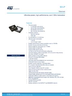
8 The block diagram of these devices is shownin Figure 1-1, the available peripherals are shown inTable 1-1 and the pinout descriptions are shown inTable and Bit Naming NAMESWhen there are multiple instances of the sameperipheral in a device, the peripheral control registerswill be depicted as the concatenation of a peripheralidentifier, peripheral instance and control identifier. Thecontrol registers section will show just one instance ofall the register names with an x in the place of theperipheral instance number. This naming conventionmay also be applied to peripherals when there is onlyone instance of that peripheral in the device to maintaincompatibility with other devices in the family thatcontain more than NAMEST here are two variants for bit names: Short name: Bit function abbreviation Long name: Peripheral abbreviation + short Bit NamesShort bit names are an abbreviation for the bit example, some peripherals are enabled with theEN bit.
9 The bit names shown in the registers are theshort name bit names are useful when accessing bits in Cprograms. The general format for accessing bits by theshort name is Forexample, the enable bit, EN, in the COG1 CON0 regis-ter can be set in C programs with the instruction, = names are generally not useful in assemblyprograms because the same name may be used bydifferent peripherals in different bit positions. When thisoccurs, during the include file generation, all instancesof that short bit name are appended with anunderscore, plus the name of the register in which thebit resides, to avoid naming 1-1:DEVICE PERIPHERAL SUMMARYP eripheralPIC12(L) f1571 pic12 (L)F1572 Analog-to-Digital Converter (ADC) Complementary Wave Generator (CWG) Digital-to-Analog Converter (DAC) Enhanced UniversalSynchronous/Asynchronous Receiver/Transmitter (EUSART) Fixed Voltage Reference (FVR) Temperature Indicator ComparatorsC1 PWM ModulesPWM1 PWM2 PWM3 TimersTimer0 Timer1 Timer2 pic12 (L) f1571 /2DS40001723D-page 8 2013-2015 Microchip Technology Bit NamesLong bit names are constructed by adding a peripheralabbreviation prefix to the short name.
10 The prefix isunique to the peripheral, thereby making every long bitname unique. The long bit name for the COG1 enable bitis the COG1 prefix, G1, appended with the enable bitshort name, EN, resulting in the unique bit name bit names are useful in both C and assembly pro-grams. For example, in C, the COG1 CON0 enable bitcan be set with the G1EN = 1 instruction. In assembly,this bit can be set with the BSF COG1 CON0,G1 ENinstruction. FieldsBit fields are two or more adjacent bits in the sameregister. Bit fields adhere only to the short bit namingconvention. For example, the three Least Significantbits of the COG1 CON0 register contain the modecontrol bits. The short name for this field is MD. Thereis no long bit name variant. Bit field access is onlypossible in C programs. The following exampledemonstrates a C program instruction for setting theCOG1 to the Push-Pull = 0x5;Individual bits in a bit field can also be accessed withlong and short bit names.