Transcription of Power MOSFET Basics: Understanding MOSFET …
1 AN605 Vishay SiliconixDocument Number: MOSFET Basics: Understanding MOSFET characteristics AssociatedWith The Figure of MeritJess Brown, Guy MoxeyINTRODUCTIONP ower mosfets have become the standard choice as themain switching device for low-voltage (<200 V) switchmodepower-supply (SMPS) converter applications. However usingmanufacturers datasheets to choose or size the correctdevice for a specific circuit topology is becoming increasinglydifficult. The main criteria for MOSFET selection are the powerloss associated with the MOSFET (related to the overallefficiency of the SMPS) and the Power -dissipation capabilityof the MOSFET (related to the maximum junction temperatureand thermal performance of the package).
2 This applicationnote focuses on the basic characteristics and understandingof the are several factors which affect the gate of theMOSFET, and it is necessary to understand the fundamentalbasis of the device structure before the MOSFET behavior canbe explained. This application note details the basic structureof the Trench MOSFET structure, identifying the parasiticcomponents and defining related terminology. It alsodescribes how and why the parasitic parameters a large variety of topologies, switching speeds, loadcurrents, and output voltages available, it has becomeimpossible to identify a generic MOSFET that offers the bestperformance across the wide range of circuit conditions.
3 Insome circumstances the on-resistance (rDS(on)) lossesdominate, and in others it is the switching losses of thetransient current and voltage waveforms, or the lossesassociated with driving the gate of the device. It also has beenshown1,2 that the input and output capacitances can be thedominant THE FIGURE OF MERIT FORMOSFET SELECTIONTo add to this confusion, device manufacturers specifyMOSFET parameters at different static and dynamicconditions, diminishing designers ability to compare like forlike. Therefore, the only true method of making the correctMOSFET choice is to compare a selection of devices withinthe circuit in which the MOSFET will be are methods available that, though sometimes difficultto implement, enable the designer to compare mosfets thatappear suited for a given application.
4 One method forevaluating mosfets is according to figure of merit. In itssimplest form, the figure of merit compares gate charge (Qg)against rDS(on). The result of this multiplication relates to acertain device technology, which is effectively scalable toachieve the required rDS(on) or Qg. However, the lower therDS(on) the higher the gate charge will be. A similar method forcomparing devices is the Baliga high-frequency figure ofmerit, BHFFOM1, which assumes that the dominantswitching loss will be associated with the charging anddischarging of the input capacitance (Ciss).
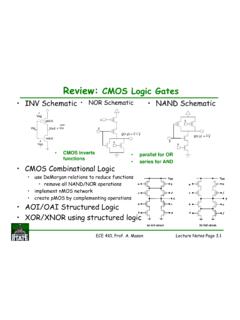
5 A third methoduses the new high-frequency figure of merit, NHFFOM2,which assumes that the dominant switching loss is due to thecharging and discharging of the output capacitance (Coss).The latter two methods are geared towards the applications inwhich the mosfets will be implemented. However, thesemethods only allow like-for-like comparisons; they do notenable the user to determine that a device with one figure ofmerit is necessarily better than a different device with 1 shows the Qg x rDS(on) figure of merit for a sample ofVishay Siliconix s range of 30-V SO-8 n- channel Si4888DY, for example, may be better in certain switchingapplications than the Si4842DY, but it is not possible to use thisgraph or other graphs using more complex figures ofmerit to determine objectively the best device for a 1.
6 Typical figure of merit for Vishay Siliconix n- channel ,30-V SO-8 MOSFETsrDS(on) (W)Gate Charge (nC)S Siliconix VGS = Electron Device Letters, Vol. 10, No. 10, October 1989, PowerSemiconductor Device Figure of Merit for High Frequency applications, B. Jayant of 1995 Int. Sym. on Power Semiconductor Devices and ICs,Hokohama, New Power Device Figure of Merit for High-FrequencyApplications, IL-Jung Kim, Satoshi Mastumoto, Tatsuo Sakai, andToshiaka Number: 7193308-Sep-03 MOSFET STRUCTURET able 1 identifies the common definitions of the majority of theMOSFET parameters and parasitics found in a 1 Definitions of MOSFET Parameters Symbol Description RB Base resistance Rg Gate resistance internal to the MOSFET Cgs Capacitance due to the overlap of the source and channelregions by the polysilicon gate.
7 Independent of appliedvoltage. Cgd Consists of two associated with the overlap of the polysilicon gate and thesilicon underneath in the JFET region. Independent ofapplied The capacitance associated with the depletion regionimmediately under the gate. Non-linear function ofvoltage. This provides a feedback loop between the output andinput circuit. It is called the Miller Capacitor because itcauses the total dynamic input capacitance to becomegreater than the sum of the static capacitors.
8 Cds Capacitance associated with the body drift diode. Variesinversely with the square root of the drain source bias. BVDSS Voltage at which the reverse-biased body drift diode breaksdown and a significant current starts to flow between sourceand drain by the avalanche multipication process, while thegate and source are shorted together. This is normallymeasured at 250-mA drain current. rDS(on) On-state resistance for Trench. EqualsRSOURCE + RCH + RA + RD + Rsub + Rwcl RSOURCE Source diffusion resistance RCH channel resistance RA Accumulation resistance RJ JFET component resistance RD Drift-region resistance Rsub Susbtrate resistance Rwcl Bond wire, contact and leadframe resistance (significant inlow-voltage devices)
9 Gfs Transconductance, a measure of the sensitivity of drainvoltage to changes in gate-source bias. Normally quoted fora VGS that gives a drain current equal to 1/2 of maximumcurrent and for VDS that ensures operation in theconstant-current : gfs is influenced by gate width, which increases inproportion as cell density increases. Reduced channel lengthis beneficial to both gfs and rDS(on). Ciss Input capacitance. Equals Cgs + Cgd with Cds shorted. Crss Reverse transfer capacitance, Cgd Coss Output capacitance.
10 Equals Cds + Cgd Qg Total gate charge. The amount of charge consumed by thecapacitance of gate Qgs Gate source charge. The charge consumed by the gatesource capacitance. Qgd Gate drain charge. The charge consumed by the gate foundations of any Power MOSFET device can be derivedfrom the vertical planar DMOS technology. Currentsemanating from the source flow laterally along the surface,then turn and flow in a perpendicular direction away from thesurface between adjacent body diffusions, through theepitaxial drain, into the substrate, and out of the waferbackside.