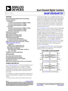
Transcription of Quad-Channel Digital Isolators Data Sheet ADuM1410 ...
1 Quad-Channel Digital Isolators Data Sheet ADuM1410 /ADuM1411/ADuM1412 FEATURES Low power operation 5 V operation mA per channel maximum at 0 Mbps to 2 Mbps mA per channel maximum at 10 Mbps 3 V operation mA per channel maximum at 0 Mbps to 2 Mbps mA per channel maximum at 10 Mbps Bidirectional communication 3 V/5 V level translation High temperature operation: 105 C Up to 10 Mbps data rate (NRZ) Programmable default output state High common-mode transient immunity: >25 kV/ s 16-lead, RoHS compliant, SOIC wide body package Safety and regulatory approvals UL recognition: 3750 V rms for 1 minute per UL 1577 CSA Component Acceptance Notice 5A VDE certificate of conformity DIN V VDE V 0884-10 (VDE V 0884-10): 2006-12 VIORM = 560 V peak T V approval: IEC/EN 60950-1 APPLICATIONS General-purpose multichannel isolation SPI interface/data converter isolation RS-232/RS-422/RS-485 transceivers Industrial field bus isolation FUNCTIONAL BLOCK DIAGRAMS ENCODEDECODEENCODEDECODEENCODEDECODEENCO DEDECODEVDD1 GND1 VIAVIBVICVIDDISABLEGND1 VDD2 GND2 VOAVOBVOCVODCTRL2 GND212345678161514131211109 ADuM141006580-001 Figure 1.
2 ADuM1410 DECODEENCODEENCODEDECODEENCODEDECODEENCO DEDECODEVDD1 GND1 VIAVIBVICVODCTRL1 GND1 VDD2 GND2 VOAVOBVOCVIDCTRL2 GND212345678161514131211109 ADuM141106580-002 Figure 2. ADuM1411 DECODEENCODEDECODEENCODEENCODEDECODEENCO DEDECODEVDD1 GND1 VIAVIBVOCVODCTRL1 GND1 VDD2 GND2 VOAVOBVICVIDCTRL2 GND212345678161514131211109 ADuM141206580-003 Figure 3. ADuM1412 GENERAL DESCRIPTION The ADuM1410 /ADuM1411/ADuM14121 are four-channel Digital Isolators based on Analog Devices, Inc., iCoupler technology. Combining high speed CMOS and monolithic air core transformer technologies, these isolation components provide outstanding performance characteristics superior to alternatives such as optocoupler devices. By avoiding the use of LEDs and photodiodes, iCoupler devices remove the design difficulties commonly associated with opto-couplers. The usual concerns that arise with optocouplers, such as uncertain current transfer ratios, nonlinear transfer functions, and temperature and lifetime effects, are eliminated with the simple iCoupler Digital interfaces and stable performance characteristics.
3 The need for external drivers and other discrete components is eliminated with these iCoupler products. Furthermore, iCoupler devices consume one-tenth to one-sixth the power of optocou-plers at comparable signal data rates. The ADuM1410 /ADuM1411/ADuM1412 Isolators provide four independent isolation channels in a variety of channel configu-rations and data rates (see the Ordering Guide) up to 10 Mbps. All models operate with the supply voltage on either side ranging from V to V, providing compatibility with lower voltage systems as well as enabling voltage translation functionality across the isolation barrier. All products also have a default output control pin. This allows the user to define the logic state the outputs are to adopt in the absence of the input p ower. Unlike other optocoupler alternatives, the ADuM1410 /ADuM1411/ ADuM1412 Isolators have a patented refresh feature that ensures dc correctness in the absence of input logic transitions and during power-up/power-down conditions.
4 1 Protected by Patents 5,952,849; 6,873,065; 6,903,578; and 7,075,329. Rev. M Document Feedback Information furnished by Analog Devices is believed to be accurate and reliable. However, no responsibility is assumed by Analog Devices for its use, nor for any infringements of patents or other rights of third parties that may result from its use. Specifications subject to change without notice. No license is granted by implication or otherwise under any patent or patent rights of Analog Devices. Trademarks and registered trademarks are the property of their respective owners. One Technology Way, Box 9106, Norwood, MA 02062-9106, Tel: 2005 2015 Analog Devices, Inc. All rights reserved. Technical Support ADuM1410 /ADuM1411/ADuM1412 Data Sheet TABLE OF CONTENTS Features .. 1 Applications .. 1 Functional Block Diagrams .. 1 General Description .. 1 Revision History .. 2 Specifications .. 3 Electrical Characteristics 5 V 3 Electrical Characteristics 3 V 5 Electrical Characteristics Mixed 5 V/3 V or 3 V/5 V Operation.
5 7 Package Characteristics .. 10 Regulatory Information .. 10 Insulation and Safety-Related Specifications .. 10 DIN V VDE V 0884-10 (VDE V 0884-10): 2006-12 Insulation Characteristics .. 11 Recommended Operating Conditions .. 11 Absolute Maximum Ratings .. 12 ESD 12 Pin Configurations and Function Descriptions .. 13 Typical Performance Characteristics .. 17 Applications Information .. 19 PC Board Layout .. 19 Propagation Delay-Related Parameters .. 19 DC Correctness and Magnetic Field Immunity .. 19 Power Consumption .. 20 Insulation Lifetime .. 20 Outline Dimensions .. 22 Ordering Guide .. 22 REVISION HISTORY 8/15 R e v. L t o R e v. M Changes to Table 5 and Table 6 .. 10 7/15 Rev. K to Rev. L Changes to Table 5 and Table 6 .. 10 4/15 R e v. J t o R e v. K Changed ADuM141x to ADuM1410 /ADuM1411/ ADuM1412 .. Throughout Change to Features Section .. 1 Changes to Table 5 and Table 6 .. 10 4/14 R e v. I t o R e v. J Change to Table 5.
6 10 3/12 Rev. H to Rev. I Created Hyperlink for Safety and Regulatory Approvals Entry in Features Section .. 1 Change to PC Board Layout Section .. 19 11/10 R e v. G t o R e v. H Added T V Approval to Features Section .. 1 Added T V Column, Table 5 .. 10 6/07 R e v. F t o R e v. G Updated VDE Certification Throughout .. 1 Changes to Features and Applications .. 1 Changes to DC Specifications in Table 1 .. 3 Changes to DC Specifications in Table 2 .. 5 Changes to DC Specifications in Table 3 .. 7 Changes to Regulatory Information Section .. 10 Adde d Ta b l e 1 0 .. 12 Added Insulation Lifetime Section .. 21 2/07 Rev. E to Rev. F Added ADuM1410 ARWZ .. Universal Updated Pin Name CTRL to CTRL2 Throughout .. 1 Changes to Ordering Guide .. 21 10/06 R e v. D t o R e v. E Added ADuM1411 and ADuM1412 .. Universal Deleted ADuM1310 .. Universal Changes to Features .. 1 Changes to Specifications Section .. 3 Updated Outline Dimensions.
7 20 Changes to Ordering Guide .. 20 3/06 R e v. C t o R e v. D Added Note 1 and Changes to Figure 2 .. 1 Changes to Absolute Maximum Ratings .. 11 11/05 Revision C: Initial Version Rev. M | Page 2 of 22 Data Sheet ADuM1410 /ADuM1411/ADuM1412 SPECIFICATIONS ELECTRICAL CHARACTERISTICS 5 V OPERATION V VDD1 V, V VDD2 V; all minimum/maximum specifications apply over the entire recommended operation range, unless otherwise noted; all typical specifications are at TA = 25 C, VDD1 = VDD2 = 5 V. All voltages are relative to their respective ground. Table 1. Parameter Symbol Min Typ Max Unit Test Conditions/Comments DC SPECIFICATIONS Input Supply Current per Channel, Quiescent IDDI (Q) mA Output Supply Current per Channel, Quiescent IDDO (Q) mA ADuM1410 , Total Supply Current, Four Channels1 DC to 2 Mbps VDD1 Supply Current IDD1 (Q) mA DC to 1 MHz logic signal frequency VDD2 Supply Current IDD2 (Q) mA DC to 1 MHz logic signal frequency 10 Mbps (BRWZ Version Only) VDD1 Supply Current IDD1 (10) 12 mA 5 MHz logic signal frequency VDD2 Supply Current IDD2 (10) mA 5 MHz logic signal frequency ADuM1411, Total Supply Current, Four Channels1 DC to 2 Mbps VDD1 Supply Current IDD1 (Q) mA DC to 1 MHz logic signal frequency VDD2 Supply Current IDD2 (Q) mA DC to 1 MHz logic signal frequency 10 Mbps (BRWZ Version Only) VDD1 Supply Current IDD1 (10) mA 5 MHz logic signal frequency VDD2 Supply Current IDD2 (10)
8 MA 5 MHz logic signal frequency ADuM1412, Total Supply Current, Four Channels1 DC to 2 Mbps VDD1 or VDD2 Supply Current IDD1 (Q), IDD2 (Q) mA DC to 1 MHz logic signal frequency 10 Mbps (BRWZ Version Only) VDD1 or VDD2 Supply Current IDD1 (10), IDD2 (10) mA 5 MHz logic signal frequency All Models Input Currents IIA, IIB, IIC, IID, ICTRL1, ICTRL2, IDISABLE 10 + +10 A 0 V VIA, VIB, VIC, VID VDD1 or VDD2, 0 V VCTRL1, VCTRL2 VDD1 or VDD2, 0 V VDISABLE VDD1 Logic High Input Threshold VIH V Logic Low Input Threshold VIL V Logic High Output Voltages VOAH, VOBH, VOCH, VODH (VDD1 or VDD2) V IOx = 20 A, VIx = VIxH (VDD1 or VDD2) V IOx = 4 mA, VIx = VIxH Logic Low Output Voltages VOAL, VOBL, VOCL, VODL V IOx = 20 A, VIx = VIxL V IOx = 400 A, VIx = VIxL V IOx = 4 mA, VIx = VIxL Rev. M | Page 3 of 22 ADuM1410 /ADuM1411/ADuM1412 Data Sheet Parameter Symbol Min Typ Max Unit Test Conditions/Comments SWITCHING SPECIFICATIONS ADuM1410 ARWZ/ADuM1411 ARWZ/ ADuM1412 ARWZ Minimum Pulse Width2 PW 1000 ns CL = 15 pF, CMOS signal levels Maximum Data Rate3 1 Mbps CL = 15 pF, CMOS signal levels Propagation Delay4 tPHL, tPLH 20 65 100 ns CL = 15 pF, CMOS signal levels Pulse Width Distortion, |tPLH tPHL|4 PWD 40 ns CL = 15 pF, CMOS signal levels Propagation Delay Skew5 tPSK 50 ns CL = 15 pF, CMOS signal levels Channel-to-Channel Matching6 tPSKCD/OD 50 ns CL = 15 pF, CMOS signal levels ADuM1410 BRWZ/ADuM1411 BRWZ/ ADuM1412 BRWZ Minimum Pulse Width2 PW 100 ns CL = 15 pF, CMOS signal levels Maximum Data Rate3 10 Mbps CL = 15 pF, CMOS signal levels Propagation Delay4 tPHL, tPLH 20 30 50 ns CL = 15 pF, CMOS signal levels Pulse Width Distortion, |tPLH tPHL|4 PWD 5 ns CL = 15 pF, CMOS signal levels Change vs.
9 Temperature 5 ps/ C CL = 15 pF, CMOS signal levels Propagation Delay Skew5 tPSK 30 ns CL = 15 pF, CMOS signal levels Channel-to-Channel Matching, Codirectional Channels6 tPSKCD 5 ns CL = 15 pF, CMOS signal levels Channel-to-Channel Matching, Opposing-Directional Channels6 tPSKOD 6 ns CL = 15 pF, CMOS signal levels All Models Output Rise/Fall Time (10% to 90%) tR/tF ns CL = 15 pF, CMOS signal levels Common-Mode Transient Immunity at Logic High Output7 |CMH| 25 35 kV/ s VIx = VDD1 or VDD2, VCM = 1000 V, transient magnitude = 800 V Common-Mode Transient Immunity at Logic Low Output7 |CML| 25 35 kV/ s VIx = 0 V, VCM = 1000 V, transient magnitude = 800 V Refresh Rate fr Mbps Input Enable Time8 tENABLE s VIA, VIB, VIC, VID = 0 V or VDD1 Input Disable Time8 tDISABLE s VIA, VIB, VIC, VID = 0 V or VDD1 Input Dynamic Supply Current per Channel9 IDDI (D) mA/ Mbps Output Dynamic Supply Current per Channel9 IDDO (D) mA/ Mbps 1 The supply current values for all four channels are combined when running at identical data rates.
10 Output supply current values are specified with no output load present. The supply current associated with an individual channel operating at a given data rate can be calculated as described in the Power Consumption section. See Figure 8 through Figure 10 for information on per-channel supply current as a function of data rate for unloaded and loaded conditions. See Figure 11 through Figure 15 for total VDD1 and VDD2 supply currents as a function of data rate for ADuM1410 /ADuM1411/ADuM1412 channel configurations. 2 The minimum pulse width is the shortest pulse width at which the specified pulse width distortion is guaranteed. 3 The maximum data rate is the fastest data rate at which the specified pulse width distortion is guaranteed. 4 tPHL propagation delay is measured from the 50% level of the falling edge of the VIx signal to the 50% level of the falling edge of the VOx signal. tPLH propagation delay is measured from the 50% level of the rising edge of the VIx signal to the 50% level of the rising edge of the VOx signal.