Transcription of Serial Peripheral Interface (SPI) with Audio Codec Support
1 2013 Microchip Technology 1 HIGHLIGHTSThis section of the manual contains the following .. and Control Registers .. of Operation .. Protocol Interface .. in Power-Saving and Debug of Various Resets .. Using SPI Modules .. Application Revision History .. 60 Serial Peripheral Interface (SPI) with Audio Codec SupportdsPIC33/PIC24 Family Reference ManualDS70005136A-page 2 2013 Microchip Technology Serial Peripheral Interface (SPI) module is a synchronous Serial Interface useful forcommunicating with external peripherals and other microcontroller devices.
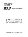
2 These peripheraldevices may be a Serial EEPROM, shift register, display driver, Analog-to-Digital Converter(ADC) or an Audio Codec . The dsPIC33/PIC24 family SPI module is compatible with Motorola SPI and SIOP interfaces. Figure 1-1 shows a block diagram of the SPI of the key features of this module are: Master and Slave modes Support Four different clock formats Framed SPI protocol Support Standard and Enhanced Buffering modes (Enhanced Buffering mode is not available on all devices) User-configurable 8-bit, 16-bit and 32-bit data width Two separate shift registers for transmission and reception SPIx receive and transmit buffers are FIFO buffers, which are 4/8/16-deep in Enhanced Buffering mode User-configurable variable data width, from 2 to 32-bit Programmable interrupt event on every 8-bit, 16-bit and 32-bit data transfer Audio Protocol Interface modeSome dsPIC33/PIC24 devices Support Audio Codec Serial protocols, such as Inter-IC Sound(I2S), Left Justified, Right Justified and PCM/DSP modes for 16, 24 and 32-bit Audio data.
3 Referto the specific device data sheet for availability of these SPI Serial Interface consists of four pins: SDIx: Serial Data Input SDOx: Serial Data Output SCKx: Shift Clock Input or Output SSx: Active-Low Slave Select or Frame Synchronization I/O PulseNote:This family reference manual section is meant to serve as a complement to devicedata sheets. Depending on the device variant, this manual section may not apply toall dsPIC33/PIC24 consult the note at the beginning of the Serial Peripheral Interface (SPI) chapter in the current device data sheet to check whether this documentsupports the device you are data sheets and family reference manual sections are available fordownload from the Microchip Worldwide Web site at: 2013 Microchip Technology 3 Serial Peripheral Interface (SPI) with Audio Codec SupportFigure 1-1.
4 SPIx Module Block DiagramInternalData BusSDIxSDOxSSxSCKxSPIxRXSR(2)ShiftContro lEnable Master ClockTransmitSPIxRXB(1)ReceiveNote 1:The SPIx Receive Buffer (SPIxRXB) and SPIx Transmit Buffer (SPIxTXB) registers are accessed through the SPIxBUF register and are multi-element FIFO buffers in Enhanced Buffer mode (pointer arithmetic is circular for these buffers). Enhanced Buffer mode is not available on all devices. Refer to the specific device data sheet for :The SPIx Shift register is not directly accessible by application :When the CPU Read Pointer (CRPTR) is less than or equal to the SPI Write Pointer (SWPTR), the CRPTR is incremented when the application reads a data element from the SPIxRXB register and the SWPTR is incremented when a data element is moved from the SPIxRXSR register to the SPIxRXB :The SPI Read Pointer (SRPTR) is less than or equal to the CPU Write Pointer (CWPTR).
5 The CWPTR is incremented when the application writes a new data element to the SPIxBUF register and the SRPTR is incremented when data is moved from the SPIxTXB register to the SPIxTXSR (4)SRPTRSWPTR(3)CRPTRSPIxBUFMSBEdgeSelec tTXELM<5:0>URDTENMSBSPIxTXSR(2)SPIxTXB(1)WriteSlave SelectSync Controland FrameClockControlClockControlSPIxURDTG eneratorBaud RateEdgeSelectdsPIC33/PIC24 Family Reference ManualDS70005136A-page 4 2013 Microchip Technology Mode SPI OperationIn Normal mode operation, the SPI master controls the generation of the Serial clock. The num-ber of output clock pulses corresponds to the transfer data width: 8, 16 or 32 bits, or dependingupon variable data width configuration, from 2 to 32-bit.
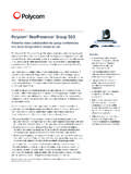
6 Figure 1-2 and Figure 1-3 illustrate SPImaster-to-slave and slave-to-master device 1-2:Typical SPIx Master-to-Slave Device Connection DiagramFigure 1-3:Typical SPIx Slave-to-Master Device Connection DiagramSDOxSDIxdsPIC33/PIC24 Serial ClockNote 1:In Normal mode, the usage of the Slave Select pin (SSx) is :Control of the SDOx pin can be disabled for Receive Only Select(1)SDIxSDOx(2)PROCESSOR 2 SSxSCKx[SPI Master][Slave]SDOx(2)SDIxdsPIC33/PIC24 Serial ClockNote 1:In Normal mode, the usage of the Slave Select pin (SSx) is :The control of the SDOx pin can be disabled for Receive Only Select(1)SDIxSDOxPROCESSOR 2 SSx/GPIOSCKx[SPI Slave][Master] 2013 Microchip Technology 5 Serial Peripheral Interface (SPI) with Audio Codec Mode SPI OperationIn Framed mode operation, the frame master controls the generation of the Frame Synchroniza-tion pulse.
7 The SPI clock is still generated by the SPI master and is continuously 1-4 and Figure 1-5 illustrate SPI frame master and frame slave device 1-4:Typical SPIx Master, Frame Master Connection DiagramFigure 1-5:Typical SPIx Master, Frame Slave Connection DiagramSDOxSDIxdsPIC33/PIC24 Serial ClockNote 1:In Framed SPI mode, the SSx pin is used to transmit/receive the frame synchronization :Framed SPI mode requires the use of all four pins ( , using the SSx pin is not optional).SSxSCKxFrame SyncPulse(1,2)SDIxSDOxPROCESSOR 2 SSxSCKx[SPI Master, Frame Master][SPI Slave, Frame Slave]SDOxSDIxSerial ClockSSxSCKxFrame SyncSDIxSDOxSSxSCKxdsPIC33/PIC24[SPI Master, Frame Slave]PROCESSOR 2[SPI Slave, Frame Master]Pulse(1,2)Note 1:In Framed SPI mode, the SSx pin is used to transmit/receive the frame synchronization :Framed SPI mode requires the use of all four pins ( , using the SSx pin is not optional).
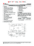
8 DsPIC33/PIC24 Family Reference ManualDS70005136A-page 6 2013 Microchip Technology Protocol Interface Mode IN Audio MASTER MODE CONNECTED TO A Codec SLAVE Figure 1-6 shows the Bit Clock (BCLK) and Left/Right Channel Clock (LRCK) as generated bythe dsPIC33/PIC24 SPI 1-6:Master Generating its Own Clock Output BCLK and IN Audio SLAVE MODE CONNECTED TO A Codec MASTER Figure 1-7 shows the BCLK and LRCK as generated by the Codec 1-7: Codec Device as Master Generates Required Clock via External AND CONTROL REGISTERSThe SPI module consists of the following Special Function Registers (SFRs): SPIxCON1L, SPIxCON1H and SPIxCON2L: SPIx Control Registers SPIxSTAT1L and SPIxSTAT1H: SPIx Status Registers SPIxBUFL and SPIxBUFH: SPIx Buffer Registers SPIxBRGL and SPIxBRGH: SPIx Baud Rate Registers SPIxIMSKL and SPIxIMSKH: SPIx Interrupt Mask Registers SPIxURDTL and SPIxURDTH.
9 SPIx Underrun Data RegistersSCKx (BCLK)SSx (LRCK)SDIxSDOxBCLKLRCKADCDATDACDATdsPIC3 3/PIC24[SPI Master] Codec [Slave]InternalClockSCKx (BCLK)SSx (LRCK)SDIxSDOxBCLKLRCKADCDATDACDATdsPIC3 3/PIC24[SPI Slave] Codec [Master]Note:Each dsPIC33/PIC24 family device variant may have one or more SPI modules. An x used in the names of pins, control/status bits and registers denotes the particularmodule. Refer to the specific device data sheets for more details. 2013 Microchip Technology 7 Serial Peripheral Interface (SPI) with Audio Codec SupportRegister 2-1:SPIxCON1L: SPIx Control Register 1 LowR/W-0U-0R/W-0R/W-0R/W-0R/W-0R/W-0R/W- 0 SPIEN(3) SPISIDLDISSDOMODE32(1,4)MODE16(1,4)SMPCK E(1)bit 15bit 8R/W-0R/W-0R/W-0R/W-0R/W-0R/W-0R/W-0R/W- 0 SSEN(2)CKPMSTENDISSDIDISSCKMCLKEN(3)SPIF EENHBUFbit 7bit 0 Legend:R = Readable bitW = Writable bitU = Unimplemented bit, read as 0 -n = Value at POR 1 = Bit is set 0 = Bit is clearedx = Bit is unknownbit 15 SPIEN.
10 SPIx On bit(3)1 = Enables module0 = Turns off and resets module, disables clocks, disables interrupt event generation and allows SFRmodificationsbit 14 Unimplemented: Read as 0 bit 13 SPISIDL: SPIx Stop in Idle Mode bit1 = Halts in CPU Idle mode0 = Continues to operate in CPU Idle modebit 12 DISSDO: Disable SDOx Output Port bit1 = SDOx pin is not used by the module; pin is controlled by the port function 0 = SDOx pin is controlled by the modulebit 11-10 MODE<32,16>: Serial Word Length bits(1,4)AUDEN = 0:AUDEN = 1:bit 9 SMP: SPIx Data Input Sample Phase bitMaster Mode:1 = Input data is sampled at the end of data output time0 = Input data is sampled at the middle of data output timeSlave Mode:Input data is always sampled at the middle of data output time, regardless of the SMP 1:When AUDEN = 1, this module functions as if CKE = 0, regardless of its actual :When FRMEN = 1, SSEN is not :MCLKEN can only be written when the SPIEN bit =.