Transcription of Series 10 Steering Control Unit - Eaton
1 Series 10 Steering Control unit Parts and Repair Information Design -002. Series 10. Steering Control unit Table of Contents Introduction ID Tag ..2. Tools ..3. Parts Assembly Drawing ..4. List ..5. Disassembly ..6-8. Assembly ..9-16. Seal Installation ..9-10. Introduction This manual provides thoroughly before with paper towels or After all repairs are service information for disconnecting the cloth lint in a complete it is essential to Char-Lynn Series 10 hydraulic lines. hydraulic system will verify the accuracy of Steering Control Units. Plug the Control unit cause damage. Control unit repairs on an Step by step instructions ports and cover open Always use new seals authorized test stand. for complete disassembly, hydraulic lines when reassembling inspection and immediately after they hydraulic Control units. reassembly of the Control have been Lubricate new rubber unit are given. disconnected. seals with a petroleum Drain the oil and clean jelly before installation.
2 The following the exterior of the Torque all bolts over recommendations should Control unit before gasketed joints, then be followed to insure making repairs. repeat the torquing successful repairs. Wash all metal parts in sequence to make up Most repairs require the clean solvent. for gasket compression. removal of the Control Use filtered, moisture- unit from the vehicle. free compressed air to Cleanliness is extremely dry the parts. important. Do not wipe them dry Clean the port areas 2 Eaton Hydraulics Series 10 Steering Control unit Parts and Repair September 2004. ID Tag Ordering Parts How to Order Each order must include the following: Replacement Parts 1. Product Number 2. Date Code 3. Part Name 4. Part Number Bar Code Label Launch Date June, 1999. 5. Quantity of Parts Refer to specific part listings Customer part number for your Char-Lynn Steering or base unit number if it Control unit when ordering has a column or valve replacement parts.
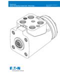
3 Listings assembled Eaton Corp. Hydraulics Div. Eden Prairie, MN 55344. are available from Eaton . Sample tag shows identification. Month / Day / Year When ordering replacement parts, you must include the Eaton Part Number following information: For additional literature contact Eaton Hydraulics at 14615 Lone Oak Road, Port Face Eden Prairie, MN 55344. Tools Tools Required For Disassembly and Assembly Screwdriver (102-152 mm [4 in. - 6 in.] long, x 3 mm [118 in.]. wide flat blade). 1/2 inch socket for current hex head cap screws. Breaker bar wrench. Torque wrench (30 Nm [300 lb-in] capacity). Special Tools: Plunger and Sleeve Tool No. 600792-001*. *Tools available by special order through our service department. Eaton Hydraulics Series 10 Steering Control unit Parts and Repair September 2004 3. Parts Assembly Drawing 1. Hex Head Screw 2. 3. 4 Low 10, 11. or 6. Medium or Standard 3. 8b 5. 8a 9. 12. Manual Steering Check Valve 3 18.
4 19. 7. 60 15. *Anti-cavitation valve parts will vary according to configuration. 13. 14. * 13. 16. 21. 21 22. 21 22. or 23. 25 or 22. 24. 23. 22. 4 Eaton Hydraulics Series 10 Steering Control unit Parts and Repair September 2004. Parts Table Parts List Series 10. Steering Control unit ITEM REFERENCE. NO. PART NO. QTY. DESCRIPTION PAGE. 1 See Table 7 Cap Screw, Hex Head 6. 2 23901-000 1 Cap, End 3 5776-000 3 Seal, 72,6 mm [ in.] ID. 4 See Table 1 Gerotor, Sub-assembly 6. 5 113094-000 1 Plate, Spacer 6 112238-000 1 Drive 7 204107-XXX 1 Housing, Valve 8a 1 Control Sleeve 8b 1 Control Spool 9 15-000 1 Pin, Centering 10 112714-000 2 or 3 Spring, Spacer 11 113599-000 4 or 6 Spring, Centering 12 112737-000 1 Retainer Spring 13 14880-000 2 Bearing Race 14 5544-000 1 Bearing, Needle Thrust 15 9332-000 1 Seal 24,9 mm [.98 in.] ID. 16 844-000 1 Dust Seal 18 16026-422P 1 Pin, Roll 34,92 mm [ in.] Length 19 285020-080 1 Ball 6,35 mm [.]
5 25 in.] OD. 21 16026-436 2 Pin, Roll 40,00 mm [ in.] Length 22 18015-000 2 Ball, Check 6,35 mm [.250 in.] OD. 23 230400-000 2 Compression Spring or 4999516-000 2 Compression Spring (See main parts assembly drawing). 24 113598-000 2 Anti-cav plug retainer 25 230313-000 2 Compression Spring 60 4999651-001 1 O-ring Eaton Hydraulics Series 10 Steering Control unit Parts and Repair September 2004 5. Parts Gerotor Table ACTUAL. DISPL. REF. NO. 4 REF. NO. 29. cm3/r GEROTOR CAP SCREW. [in3/r] PART NO. Width mm[in] PART NO. LENGTH mm[in]. 60 [ ] 8618-023 10,2 [.40] 16336-514 38,1 [ ]. 75 [ ] 8618-024 10,2 [.40] 16336-514 38,1 [ ]. 95 [ ] 8618-003 13,2 [.52] 16336-515 41,3 [ ]. 120 [ ] 8618-009 16,5 [.65] 16336-516 44,5 [ ]. 145 [ ] 8618-020 20,1 [.79] 16336-517 47,6 [ ]. 160 [ ] 8618-004 21,9 [.86] 16336-520 50,8 [ ]. 185 [ ] 8618-005 25,4 [ ] 16336-521 54,0 [ ]. 230 [ ] 8618-031 31,7 [ ] 16336-523 60,3 [ ]. 295 [ ] 8618-035 40,4 [ ] 16336-525 66,7 [ ].
6 370 [ ] 8618-032 50,8 [ ] 16336-531 79,4 [ ]. 460 [ ] 8618-033 63,5 [ ] 16336-535 92,0 [ ]. 590 [ ] 8618-036 80,8 [ ] 16336-542 108,0 [ ]. 740 [ ] 8618-034 101,6[ ] 16336-551 130,2 [ ]. Disassembly Cleanliness is extremely 1. Clamp unit in vise, important when repairing a meter end up. Clamp lightly on edges of port Gerotor (Meter) End Steering Control unit . Work in a clean area. Before dis- face sides (see figure1). connecting lines, clean port Use protective material on vise jaws. Housing 25 mm area of unit thoroughly. Use [1 inch]. a wire brush to remove distortion could result if Max. foreign material and debris jaws are overtightened. from around exterior joints of the unit . We recommend that you keep the unit in a vise during disassembly. Follow the clamping procedures explained throughout the manual. Figure 1. 6 Eaton Hydraulics Series 10 Steering Control unit Parts and Repair September 2004. Disassembly Screw, Cap, Hex Head C.
7 2. Remove 5/16 in. cap Cap, End screws. p Seal 3. Remove end cap. 4. Remove seal from gerotor (meter). ly B. End Gerotor A. Figure 2. 5. Remove gerotor (meter). Gerotor Be careful not to drop star. (Meter). Attention: Do not bind 6. Remove seal from spacer Seal spool and sleeve in housing. plate. Rotate spool and sleeve 7. Remove spacer plate. Plate, Spacer assembly slowly when 8. Remove seal from housing. removing it from housing. Seal 9. Pull drive and twist to remove SP/SL drive assembly from housing. Drive 10. Remove housing from vise. Drive Spool and Sleeve Housing Figure 3. Eaton Hydraulics Series 10 Steering Control unit Parts and Repair September 2004 7. Disassembly 11. Carefully remove bearing and races, anti-cavitation Manual Steering Check Dust Seal valves and manual Valve (when applicable). Steering check valve (roll pin and ball) from bolt Ball holes by tipping housing Roll Pin Gerotor side down. (see figure 3).
8 12. Do not remove any valves other than manual Steering check Seal valve assembly and O-ring anti-cavitation valve Race assembly. All other Bearing valves are factory preset and are non-serviceable. Race * Anti-Cavitation Valves Ball for Cylinder Ports 13. Carefully Remove Seal with Reference Page 4. a thin-blade screw driver. Roll Pin Do not scratch seal groove for other configurations with screw driver. 14. Use thin bladed screw driver to pry dust seal Figure 4. from housing. Do not damage housing. 15. Push pin from spool and Standard Input Torque sleeve assembly. Spring/Spacer Package 16. Remove Drive 17. Push spool partially from Control end of sleeve, Medium Input Torque then carefully remove centering springs and Spring/Spacer Package retaining ring from spool by hand (figure 8). Low Input Torque Spring/Spacer Package *Note Standard input torque unit uses six centering springs and two spacers. Medium input torque unit uses four centering springs and three spacers.
9 Low input torque unit Figure 5. uses four centering springs and two spacers. 8 Eaton Hydraulics Series 10 Steering Control unit Parts and Repair September 2004. Assembly Assembly Cleanliness Recommendations Check all mating surfaces. Replace any parts that have scratches or burrs that could cause leakage. Clean all metal parts in clean solvent. Blow dry with air. Do not wipe dry with cloth or paper towel because lint or other matter can get into the hydraulic system and cause damage. Do not use grit paper or file or grind these parts. Note: Lubricate all seals with clean petroleum jelly. A good service policy is to replace all old seals with new seals. Do not use excessive lubricant on seals for meter section. Refer to parts lists covering your Steering Control unit when ordering replacement parts. Place housing on a flat work area on a clean lint free cloth. Install press-fit 24,9 mm[.98 in.] ID seal in housing with metal suface of seal facing toward housing (figure 6).
10 Figure 6. 2-Piece Shaft Seal Installation For installation of o-ring: 4999651-001. and Seal 9332-000. 1. Place housing on a flat work area as shown in figure 7. 2. Lubricate seal and o-ring with hydraulic oil before installation 3. Align sleeve with housing bore (figure 7). Figure 7 Tool No. 600792-001. Eaton Hydraulics Series 10 Steering Control unit Parts and Repair September 2004 9. Assembly 2-Piece Shaft Seal Installation 7. Push seal onto plunger. Lip of seal should be between o-ring and plunger. No gap should exist between o-ring 4. Insert sleeve into and seal (figure 11). housing bore (Figure 8). Figure 11. Figure 8. 8. Align plunger with sleeve (figure 12). 5. Place o-ring on plunger (Figure 9). Figure 12.. Push plunger into sleeve until it bottoms out, rotate 1/4 turn (figure 13). Figure 9 10. While holding sleeve in housing, withdraw plunger. 6. Align seal with plunger. cross section "L" shape 11. Withdraw sleeve.