Transcription of Series and Parallel Resonance - ece.rutgers.edu
1 Rutgers UniversityAuthored by P. SannutiLatest revision: December 16, 2005, 2004by P. PanayotatosSchool of EngineeringDepartment of Electrical and Computer Engineering332:224 Principles of Electrical Engineering II LaboratoryExperiment 1 Series and Parallel Resonance1 IntroductionObjectives To introduce frequency response by studying thecharacteristics of two resonant circuits on either side ofresonanceOverviewIn this experiment, the general topic of frequency response is introduced by studying thefrequency-selectivity characteristics of two specific circuit structures. The first is referred toas the Series - resonant circuit and the second as the Parallel - resonant relevant equations and characteristic bell-shaped curves of the frequency responsearound Resonance are given in section exercises are designed to enhance understanding of the concepts and calculateanticipated values subsequently measured in the and voltage are then measured in the two resonant circuits as functions of frequencyand characteristic frequencies ( Resonance and 3-dB points) are experimentally Domain AnalysisIn electrical engineering and elsewhere, frequency domain analysis or otherwise known asFourier analysis has been predominantly used ever since the work of French physicist JeanBaptiste Joseph Fourier in the early 19th century.
2 The pioneering work of Fourier led towhat are now known as Fourier Series representations of periodic signals and FourierTransform representations of periodic signals. A periodic signal of interest in engineeringcan be represented in terms of a Fourier Series1 which is a weighted linear combination ofsinusoids of harmonically related frequencies. Each frequency among harmonically relatedfrequencies is an integer multiple of a particular frequency known as the fundamentalfrequency. The number of harmonically related sinusoids present in the Fourier Seriesrepresentation of a periodic signal could be finite or countably infinite. Since a periodicsignal can be viewed as being composed of a number of sinusoids, in order to specify aperiodic signal, one could equivalently specify the amplitude and phase of each sinusoidpresent in the signal.
3 Such a specification constitutes the frequency domain description of aperiodic signal. Similarly, in Fourier Transform representation, under some naturalconditions, an aperiodic signal or a signal which is not necessarily periodic can be viewed asbeing composed of uncountably infinite number of sinusoids or a continuum of sinusoids. Inthis case, instead of being a weighted sum of harmonically related sinusoids, an aperiodicsignal is a weighted integral of sinusoids of frequencies which are all not harmonicallyrelated. Again, instead of specifying an aperiodic signal in terms of the time variable t, onecan equivalently specify the amplitude and phase density of each sinusoid of frequency !contained in the signal. Such a description obviously uses the frequency variable !
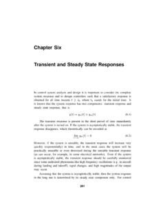
4 As anindependent variable, and thus it is said to be the frequency domain or !"domain descriptionof the given time domain signal. In this way, a time domain signal is transformed to afrequency domain signal. Of course, once the frequency domain description of a signal isknown, one can compose all the sinusoids present in the signal to form its time domaindescription. However, it is important to recognize that the frequency domain description issimply a mathematical tool. In engineering, signals exist in a physically meaningful domainsuch as time domain. The frequency domain description only serves to help for the betterunderstanding of certain signal characteristics. 1 A more detailed treatment can be found in the text starting with section ResonanceThe basic Series - resonant circuit is shown in fig.
5 1. Of interest here in how the steady stateamplitude and the phase angle of the current vary with the frequency of the sinusoidalvoltage source. As the frequency of the source changes, the maximum amplitude of thesource voltage (Vm) is held ++-VRVL+++---VCRCLiVs = Vmcos(!t) i = Imcos(!t + #)The frequency at which the reactances of the inductance and the capacitance cancel eachother is the resonant frequency (or the unity power factor frequency) of this circuit. Thisoccurs at !o=1LC (1)Since i = VR /R, then the current i can be studied by studying the voltage across the current i has the expressioni = Imcos(!t + #)where Im=VmR2+!L"1!C#$%&'(2 (2A)and !="tan"1#L"1#CR$%&&&'())) (2B)The bandwidth of the Series circuit is defined as the range of frequencies in which theamplitude of the current is equal to or greater than 1/2=2/2() times its maximumamplitude, as shown in fig.
6 2. This yields the bandwidth B = !2-!1= R/LFig. 1 The SeriesResonant CircuitPEEII-III-4/12 Where !2,1=R2L"#$%&'2+1LC R2L (3)!2,1 are called the half power frequencies or the 3 dB frequencies, the frequencies at whichthe value of Im equals the maximum possible value divided by2= quality factor Q=!oB=1 RLC (4)Then the maximum value of :1- VR occurs at ! = !o (5A)2- VL occurs at !o1"R2C2L (5B)3- VC occurs at !o1"R2C2L (5C)Im!!01!2!Imax=VmRm(2)1/2B=RL2!1!-= 2 Frequency Response of a Series - resonant CircuitPEEII-III-5 ResonanceThe basic Parallel - resonant circuit is shown in fig. 3. Of interest here in how the steady stateamplitude and the phase angle of the output voltage V0 vary with the frequency of thesinusoidal voltage source.
7 !RV0+-IsCL Is = Imcos(!t) Vo = Vmcos(!t+#)If Is = Imcos(!t), then Vo = Vmcos(!t+#) whereVm=Im1R2+!C"1!L#$%&'(2 (6A)and!="tan"1R#C"1#L$%&'()$%&'() (6B)The resonant frequency is !o=1 LCThe 3 dB frequencies are: !2,1=12RC"#$%&'2+1LC 12RC (7)The bandwidth B = !2 - !1 = 1 quality factor Q=!oB=RCL (8)Fig. 3 The ParallelResonant circuitPEEII-III-6/12!!01!2!VmB=RL2!1!-= RImIm(2)1/2 RFig. 4 Frequency Response of the Parallel - resonant More Realistic Parallel Resonance CircuitA more realistic Parallel - resonant circuit is shown in fig. 5. It is a more realistic modelbecause it accounts for the losses in the inductor through its resistance RL.)
8 !RV0+-IsLLRCIn this case : !o=1LC"RLL#$%&'(2 (9) Z(!o)=RLRLRC+L(10)andFig. 5 A More RealisticParallel - resonant CircuitPEEII-III-7/12 Vo(!o)=Is(!o)RLRLRC+L (11)An analysis of the amplitude of the output voltage as a function of frequency reveals that theamplitude is not maximum at !0. It can be derived that |V0| is maximum when! = !m = (x - y)1/2 (12)where x = (a + b)1/2 a=1LC()21+2 RLR!"#$%& b=RLL!"#$%&22LC and y=RLL!"#$%&2 This analysis can be followed by first expressing Vo as a function of !, differentiating thisexpression with respect to ! and then finding the value of ! that makes the derivative Derive equations 1, 2, 3, and 4 for the Series - resonant circuit in fig.)
9 Derive equations: 5A, 5B, and 5C for the Series - resonant circuit in fig. : | VR |=| I | R where I = Im is given by equation 2A. So VR is maximum whenIm R is maximum , Im is maximum (since R is constant). Similarly solve forVL = | I | ZL and VC = | I | ZC . For the Series - resonant circuit shown in fig. 6, use equations: 5A, 5B, and 5C to determinethe frequencies at which VR, VC, and VL+RL are ExperimentsSuggested Equipment:Tektronix FG 501A 2 MHz Function Generator2 Tektronix 504A Counter - TimerHP 54600A or Agilent 54622A OscilloscopeProtek Model B-845 Digital MultimeterLS-400A Inductance Substituter Box620 F CapacitorBreadboardOther circuit elements to be determined by the Series ResonanceAny function generator used has internal resistance.
10 Also, the inductor has internal need to be determined since all resistances affect the behavior of the generator resistanceThe internal resistance of the function generator will affect the damping of an RLC circuit towhich it is connected. Check the resistance in the following way:a- With a sine wave output, set the open circuit voltage to some convenient value, say Connect a pure variable resistance load (potentiometer) thus forming a voltage R until the terminal voltage falls to one-half the open circuit value. At this point thetwo resistances of the voltage divider have to be equal. Therefore, the resistance of thepotentiometer should now be equal to the internal resistance of the function the potentiometer from the circuit and measure its internal resistanceUse the digital ohmmeter to measure the internal resistance of the inductor Rs and =.