Transcription of Simulating Verilog RTL using Synopsys VCS
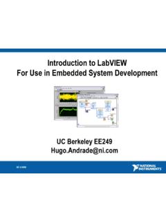
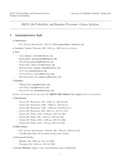
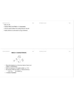
1 Simulating Verilog RTL using Synopsys VCS. CS250 Tutorial 4 (Version 092509a). September 25, 2009. Yunsup Lee In this tutorial you will gain experience using Synopsys VCS to compile cycle-accurate executable simulators from Verilog RTL. You will also learn how to use the Synopsys Waveform viewer to trace the various signals in your design. Figure 1 illustrates the basic VCS toolflow and SMIPS. toolchain. For more information about the SMIPS toolchain consult Tutorial 3: Build, Run, and Write SMIPS Programs. VCS takes a set of Verilog files as input and produces a simulator. When you execute the simulator you need some way to observe your design so that you can measure its performance and verify that it is working correctly. There are two primary ways to observe your design: (1) you can use $display statements in your Verilog RTL to output textual trace information, or (2) you can instruct the simulator to automatically write transition information about each signal in your design to a file.
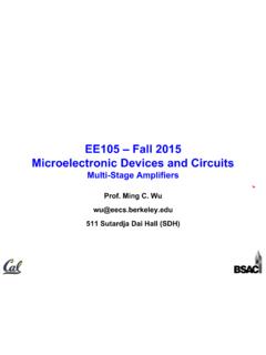
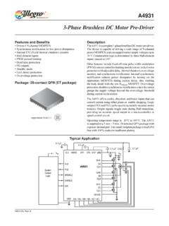
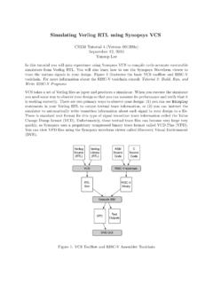
2 There is standard text format for this type of signal transition trace information called the Value Change Dump format (VCD). Unfortunately, these textual trace files can become very large very quickly, so Synopsys uses a proprietary compressed binary trace format called VCD Plus (VPD). You can view VPD files using the Synopsys waveform viewer called Discovery Visual Environment (DVE). You will be using a simple unpipelined SMIPSv1 processor as your design example for this tutorial, and thus you will also learn how to build and run test codes on the processor simulator. Figure 2. shows the block diagram for the example processor. Figure 1 shows the SMIPS toolchain which starts with an SMIPS assembly file and generates a Verilog Memory Hex (VMH) file suitable to run on the cycle-accurate simulator. This tutorial assumes you are familiar with the SMIPS ISA.
3 For more information please consult the SMIPS Processor Specification. The following documentation is located in the course locker ~cs250/docs/manuals and provides additional information about VCS, DVE, and Verilog . - VCS User Guide - VCS Quick Reference vcs - Discovery Visual Environment User Guide vcs - Unified Command Line Interface User Guide - Language specification for the original Verilog -1995. - Language specification for Verilog -2001. Getting started Before using the CS250 toolflow and SMIPS toolchain you must run the course setup script with the following command. % source ~cs250/ CS250 Tutorial 4 (Version 092509a), Fall 2009 2. Verilog Verilog ASM C. Source Libs Source Source Code Code VCS SMIPS toolchain Cycle Accurate VMH. Sim Execute Sim VPD Text Trace Output DVE GUI. Figure 1: VCS Toolflow and SMIPS Assembler Toolchain CS250 Tutorial 4 (Version 092509a), Fall 2009 3.
4 PC. eq? pc+4. +4. ir[20:16]. branch Cmp pc_sel wb_sel ir[25:21] rd0 rf_wen Instruction Mem Reg ir[20:16] rd1. File Add Reg File val ir[15:0] Sign Extend >> 2. addr rdata Data wdata Mem Control Decoder Signals rw val tohost_en tohost testrig_tohost Figure 2: Block diagram for Unpipelined SMIPSv1 Processor For this tutorial you will be using an unpipelined SMIPSv1 processor as your example RTL design. You should create a working directory and copy files from the course locker using the following commands. % mkdir tut1. % cd tut1. % cp -R ~cs250/examples/v-smipsv1-1stage/* . Before starting, take a look at the subdirectories in the project directory. All of your projects will have a similar structure. Source RTL should be placed in the src directory and test input files should be placed in the smips-tests directory.
5 The build directory will contain all generated content including simulators, synthesized gate-level Verilog , and final layout. In this course you will always try to keep generated content separate from your source RTL. This keeps your project directories well organized, and helps prevent you from unintentionally modifying your source RTL. There are subdirectories in the build directory for each major step in the CS250 toolflow. These subdirectories will contain scripts and configuration files necessary for running the tools required for that step in the toolflow. For example, the build/vcs-sim-rtl directory contains a makefile which can build Verilog simulators and run tests on these simulators. You should browse the source code for the processor in src to become familiar with the design. The example code makes use of the simple Verilog component library (VCLIB) located in ~cs250/install/vclib.
6 VCLIB includes a variety of muxes, flip-flops, latches, RAMs, memories, and queues. You are welcome to either use the globally installed VCLIB or to create your own component library. CS250 Tutorial 4 (Version 092509a), Fall 2009 4. Compiling the Simulator In this section you will first see how to run VCS from the command line, and then you will see how to automate the process using a makefile. To build the simulator you need to run the vcs compiler with the appropriate command line arguments and a list of input Verilog files. % cd build/vcs-sim-rtl % vcs -PP +lint=all +v2k -timescale=1ns/10ps \. -v ~cs250/install/ \. -v ~cs250/install/ \. -v ~cs250/install/ \. -v ~cs250/install/ \../../ \../../ \../../ \../../ \../../ \../../ \../../ By default, VCS generates a simulator named simv. The -PP command line argument turns on support for using the VPD trace output format.
7 The +lint=all argument turns on Verilog warnings. Since it is relatively easy to write legal Verilog code which is probably functionally incorrect, you will always want to use this argument. For example, VCS will warn you if you connect nets with different bitwidths or forget to wire up a port. Always try to eliminate all VCS compilation errors and warnings. Since you will be making use of various Verilog -2001 language features, you need to set the +v2k command line option so that VCS will correctly handle these new constructs. Verilog allows a designer to specify how the abstract delay units in their design map into real time units using the timescale compiler directive. To make it easy to change this parameter you will specify it on the command line instead of in the Verilog source. After these arguments you list the Verilog source files.
8 You use the -v flag to indicate which Verilog files are part of a library (and thus should only be compiled if needed) and which files are part of the actual design (and thus should always be compiled). After running this command, you should see text output indicating that VCS is parsing the Verilog files and compiling the modules. Notice that VCS actually generates ANSI C. code which is then compiled using gcc. When VCS is finished you should see a simv executable in the build directory. Typing in all the Verilog source files on the command line can be very tedious, so you will use makefiles to help automate the process of building your simulators. The following commands will first delete the simulator you previously built, and then regenerate it using the makefile. % rm -f simv % make CS250 Tutorial 4 (Version 092509a), Fall 2009 5.
9 The make program uses the Makefile located in the current working directory to generate the file given on the command line. Take a look at the Makefile located in build/vcs-sim-rtl. Makefiles are made up of variable assignments and a list of rules in the following form. target : dependency1 dependency2 .. dependencyN. command1. command2.. commandN. Each rule has three parts: a target, a list of dependencies, and a list of commands. When a desired target file is out of date or does not exist, then the make program will run the list of commands to generate the target file. To determine if a file is out of date , the make program compares the modification times of the target file to the modification times of the files in the dependency list. If any dependency is newer than the target file, make will regenerate the target file.
10 Locate in the makefile where the Verilog source files are defined. Find the rule which builds simv. More information about makefiles is online at Not all make targets need to be actual files. For example, the clean target will remove all gener- ated content from the current working directory. So the following commands will first delete the generated simulator and then rebuild it. % make clean % make simv Building SMIPS Test Assembly Programs A test program called smipsv1 is located locally in the smips-tests directory. If you want to add your own test programs, you would add them to this directory. There are additional globally installed SMIPS assembly test programs located in ~cs250/install/smips-tests which you can use for your lab assignments and projects. The following command will build all of the local tests and run it on the SMIPSv2 ISA simulator.