Transcription of Software Phase Locked Loop Design Using C2000 ...
1 ApplicationReportSPRABT4A November2013 SoftwarePhaseLockedLoopDesignUsingC2000 Microcontrollersfor ThreePhaseGridConnectedApplicationsManis hBhardwajABSTRACTG ridconnectedapplicationsrequirean accurateestimateof the grid angleto feedpowersynchronoustothe is achievedusinga softwarephaselockedloop(PLL).Thisapplica tionreportdiscussesthedifferentchallenge sin the designof softwarephaselockedloopsfor threephasegrid connectedinvertersand presentsa methodologyto illustrate,two well knownPLL structures[1], [2] are discussedand ControlSuite .. of Figures1 Transformationof VoltageFromThreePhaseto Stationaryand TransformsFromThreePhaseto 3ph-Basedon Responseto VaryingGrid NegativeSequenceof Responseto VaryingGrid phaseangleof the utilityis a criticalpieceof informationfor the operationof powerdeviceslike PVInvertersthat feedpowerinto the PLL is a closedloop systemin whichan internaloscillatoriscontrolledto keepthe time and phaseof an externalperiodicalsignalusinga qualityof the lock directlyaffectsthe performanceof the controlloop in grid tied line notching,voltageunbalance,line dips,phaseloss and frequencyvariationsare commonconditionsfacedbyequipmentinterfac ingwith the PLL needsto be able to rejectthesesourcesof errorandmaintaina cleanphaselock to the grid .
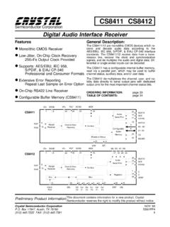
2 ControlSuiteare trademarksof othertrademarksare the propertyof November2013 SoftwarePhaseLockedLoopDesignUsingC2000 MicrocontrollersforThreePhaseGrid ConnectedApplicationsSubmitDocumentation FeedbackCopyright 2013,TexasInstrumentsIncorporated000 0cos( ) sin( ) 0sin( ) cos( ) 000 1 VTVdqdqvvdvX vqvvooababqqaqqb= = - 001 cos(2 3) cos(4 3)cos( )220 sin(2 3) sin(4 3)sin( )331110222 VTVabcabcVVtaVX Vt VbVcVoababppwappwb= == aVbVcVAlphaBetadqVnetqw32p-34p-cos( )cos(- 2 / 3)cos(- 4 / 3)VtaVVtbwtVcwwpp = threephasesystems,it is commonto transformthreephasetime varyingquantitiesto a dc system(in arotatingreferenceframe).Equation1 showsthat the sequenceof the voltagesis Va Vc Vband the frequencyis .(1)Figure1. Transformationof VoltageFromThreePhaseto Stationaryand RotatingReferenceFrameFor transformingthe threephasequantitiesto rotatingreferenceframe,the first step is to transformthethreephasequantitiesinto an orthogonalcomponentsystem(alpha,betaalso calledstationaryreferenceframe)by takingthe projectionsof the threephasequantitieson an is calledtheClarketransform(seeEquation2).
3 (2)In the stationaryreferenceframe,the net voltagevectormakesan angle with the orthogonalreferenceframeand rotatesat a frequencyof . The systemcan thenbe reducedto DC by takingthe projectionofthe stationaryreferenceframecomponentson the is calledthe Parktransform(seeEquation3).(3)2 SoftwarePhaseLockedLoopDesignUsingC2000 MicrocontrollersforSPRABT4A November2013 ThreePhaseGrid ConnectedApplicationsSubmitDocumentation FeedbackCopyright 2013,TexasInstrumentsIncorporatedcos()2s in()30vtdvtqvowqwq - =- cos( ) sin( ) 0 cos( )cos( ) * cos( ) sin( )sin( )22sin( ) cos( ) 0sin( )sin( ) * cos( ) cos( )sin( )3300 100vtttdvXt Vtt Vqvoqqwqwqwqqwqwqw + =-=-+ Phase Reference Frame Projection (Clarke Transform) Reference Frame Projection (Park Transform) Simulationof TransformsFromThreePhaseto RotatingReferenceFrame2 SynchronousReferenceFramePLLThe role of the PLL in threephasecontextis to accuratelyestimatethe anglethe net voltagevectorismakingby measuringthe anglethe PLL estimatesis and the actualangleis *t, ABC->DQ0transformcan be writtenusingEquation2 and Equation3.
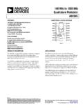
4 (4)Usingtrigonometricidentities,Equation 5 can be reducedto:(5)WhenPLL angleis closeto the actualvoltagevectorangle,( *t- ) is smallor closeto zerothensin( *t- ) ~ = ( *t- ). Therefore,it can be said for a balancedthreephasesystemwhenPLL is Locked ,the q-axiscomponentin the rotatingreferenceframereducesto zeroand whenit is not lockedor has smallerrortheq-axiscomponentis linearlyproportionalto the error:Vq (wt )(6)This propertyis usedin the SynchronousReferenceFramePLL for threephasegrid threephasequantitiesare transformedinto the rotatingreferenceframeand the qcomponentis usedas the low passfilter/PIis thenusedto eliminatesteadystateerrorand the outputfed to a VCO,whichgeneratesthe angleand sine November2013 SoftwarePhaseLockedLoopDesignUsingC2000 MicrocontrollersforThreePhaseGrid ConnectedApplicationsSubmitDocumentation FeedbackCopyright 2013,TexasInstrumentsIncorporated1( )0 1*1( )1ylf zBBzynotch zz-+=--[ ] [ 1] * 1[ ] * 0[ 1] * 1ylf nylf nAynotch nBynotch nB=-++-4vKgrid pnTivT Kgrid i pwz==22( )222snnH sssnnzwwzww+=++: ()( )( )( )( )( )22( )( )1( )(.)
5 ( )2kpvk sgridpsTLF soutiHsokClosed loop Phase TFClosed loop error transferssLF spinsvk svgrid pgridTiVsssdEsHsookssLF spinfunctiok sTinspqqq+===+++= -==+++Measure Vgridnf)sin(_inagridavv6 ipkkLPF+of1/sout6cosSinVCOABC->DQ0 TransformDvQv)32sin(_56 inbgridbvv)34sin(_56 SPLLfor 3ph-Basedon StationaryReferenceFrameIt is knownfromEquation6 that any errorin the anglelock will showup on the q termand that the relationbetweenthe errorfor smallvaluesis linear,see Equation7:err Vgrid( grid - PLL)(7)Smallsignalanalysisis doneusingthe networktheory,wherethe feedbackloop is brokento get the openloop transferequationand thenthe closedloop transferfunctionis givenby:ClosedLoopTF = OpenLoopTF / (1+ OpenLoopTF)(8)The PLL transferfunctioncan be writtenas follows:(9)Comparingthe closedloop phasetransferfunctionto the genericsecondordersystemtransferfunction :(10)Now,comparingthis with the closedloop phasetransferfunction,the naturalfrequencyand the dampingrationof the lineralizedPLL is givenas:(11) PI ControllerThe loop filter or PI is implementedas a digitalcontrolleras shownin Equation12:(12)Usingz transform,Equation13 can be re-writtenas:(13)4 SoftwarePhaseLockedLoopDesignUsingC2000 MicrocontrollersforSPRABT4A November2013 ThreePhaseGrid ConnectedApplicationsSubmitDocumentation FeedbackCopyright 2013,TexasInstrumentsIncorporated2 **2 **0and 122 KKTKKT pipiBB-+ == - 111* ln( )2 Whereandand1sscttcecetsncndndsssswsVwwV ww--- = - = ====-( ) 1sin()ty tcetdswj-= -+2( )222nH sssnnwzww=++2 **2 **122( )1( )1 KKTKKT pipizylf zynotch zz+- -- =--21( )1zsT z-=+( )( )Kylf siKpynotch ss=+ is knownthat the LaplaceTransformof the loop filter (PI controller)is givenby.
6 (14)Now,usingBi-lineartransformation,rep lace, whereT = SamplingTime.(15)Equation2 and Equation3 can be comparedto mapthe proportionaland integralgain of the PI controllerinto the next challengeis selectingan appropriatevaluefor the is knownthat the step responseto a generalsecondorderequation:(16)is givenas:(17)Ignoringthe LHPzerofromEquation17, the settlingtime is givenas the time it takesfor the responsetosettlebetweenan errorband,say this erroris , then:(18)Usingsettlingtime of 30 ms, errorbandof 5% and dampingratioof , the naturalfrequencyof be obtained;and thenbacksubstitutingyou get Kp= K1= the digitalloop filter coefficients,you get:(19)For 10 Khz,run rate for the PLL,B0 = B1 = - November2013 SoftwarePhaseLockedLoopDesignUsingC2000 MicrocontrollersforThreePhaseGrid ConnectedApplicationsSubmitDocumentation FeedbackCopyright 2013, PhaseLockedLoopfor VaryingConditionsBeforecodingthe SPLL structure,it is essentialto simulatethe behaviorof the PLL for differentconditionson the usedfor lowercost in manygrid tied Mathis aconvenientway to look at fixedpointnumberswith a mathlibraryprovidesbuilt infunctionsthat can simplifyhandlingof the decimalpointby the usedtosimulateand identifythe Q pointthe algorithmneedsto be run at.
7 Belowis the MATLAB scriptusingthefixedpointtool box that teststhe PLL algorithmwith varyinggrid 3ph Modeling%%%%%%%%%%%%%%%%%%%%%%%%%%%%%%%% %% TexasInstruments% DigitalControlSystemsGroup,Houston,TX% ManishBhardwaj%%%%%%%%%%%%%%%%%%%%%%%%%% %%%%%%%%%%%%%%%%%%%%%%%%%%%%%%%%%%%%%%%% %%%%%%%%%%%%%%%%%%%%%%%%%%%%%%%%%%%%%%%% %%%%%%%%%%%%%%%%%%%%%%%%%%%%%%%%%%%%%%%% %%%%%%%%%%%%%%%%%%%%%%%%%%%%%%%%%%%%%%%% %%%%%%%%%%%%%%%%%%%%%%%%%%%%%% Thissoftwareis licensedfor use withTexasInstrumentsC28x% providedto you priorto installing% the ---------------------------------------- --------------------------------%Copyrig ht(C) 2010-2012 TexasInstruments, ;closeall;clc;%Selectnumerictype,T=numer ictype('WordLength',32,'FractionLength', 22);%Specifymathattributesto the fimathobjectF=fimath('RoundMode','floor' ,'OverflowMode','wrap'); 'SpecifyPrecision'; ; ; 'SpecifyPrecision'; ; ;%specifyfiprefobject,to displaywarningin casesof overflowand%underflowP=fipref; 'on'; 'none'; 'none';%PLLM odellingstartsfromhereFs=10000;Ts=1/Fs;% SamplingTime= (1/fs), NoteTs is relatedto the frequency% the ISR wouldrun in the solarapplicationas well,assuming% 10 Khzcontrolloopfor the inverterTfinal= ;% Totaltimethe simulationis run fort=0:Ts:Tfinal;% timevectorGridFreq=60;% nominalgridfrequencywn=2*pi*GridFreq;% nominalfrequencyin radiansfn=GridFreq;wu=2*pi*GridFreq;thet a=rem((t*2*pi*GridFreq),2*pi);L=length(t );%generateinputsignaland createa fi objectof it% CASE1 : PhaseJumpat the Mid Point%6 SoftwarePhaseLockedLoopDesignUsingC2000 MicrocontrollersforSPRABT4A November2013 ThreePhaseGrid ConnectedApplicationsSubmitDocumentation FeedbackCopyright 2013, for n=1:floor(L/2)%Ua(n)=cos(theta(n));%Ub(n )=cos(theta(n)-2*pi/3);%Uc(n)=cos(theta( n)-4*pi/3).
8 % end% for n=floor(L/2):L%Ua(n)=cos(theta(n)+ );%Ub(n)=cos(theta(n)-2*pi/3+ );%Uc(n)=cos(theta(n)-4*pi/3+ );% end% Ua_ideal=Ua;%CASE2: UnbalancedGridUa_ideal=cos(theta);Ua=fi( Ua,T,F);Ub=fi(Ub,T,F);Uc=fi(Uc,T,F);Ua_i deal=fi(Ua_ideal,T,F);%declarearraysused by the PLL processylf =fi([0,0],T,F);u_q =fi([0,0],T,F);Theta=fi([0,0,0],T,F);fo= fi(0,T,F);Ualpha=fi([0,0],T,F);Ubeta=fi( [0,0],T,F);Ud_plus=fi([0,0],T,F);Uq_plus =fi([0,0],T,F);fn=fi(fn,T,F);wo=fi(0,T,F );% simulatethe PLL processfor n=3:L% No of iterationof the PLL processin the simulationtimeUalpha(n)=fi(( ),T,F)*(Ua(n)-fi( ,T,F)*(Ub(n)+Uc(n)));Ubeta(n)=fi(( )* ,T,F)*(Ub(n)-Uc(n));Ud_plus(n)=Ualpha(n) *cos(Theta(n))+Ubeta(n)*sin(Theta(n));Uq _plus(n)=-Ualpha(n)*sin(Theta(n))+Ubeta( n)*cos(Theta(n));u_q(1)=Uq_plus(n);%Loop Filterylf(1)=ylf(2)+fi( ,T,F)*u_q(1)-fi( ,T,F)*u_q(2);%ylf(1)=ylf(2)+fi( ,T,F)*u_q(1)-fi( ,T,F)*u_q(2);ylf(1)=min([ylf(1)fi( ,T,F)]);%updateu_q for futureuseu_q(2)=u_q(1);ylf(2)=ylf(1);%up dateoutputfrequencyfo=fn+ylf(1);Theta(n+ 1)=Theta(n)+fi(2*pi,T,F)*(fo*Ts);if(Thet a(n+1)>=(fi(2*pi,T,F)-fi(2*pi,T,F)*(fo*T s)))Theta(n+1)=0;endend7 SPRABT4A November2013 SoftwarePhaseLockedLoopDesignUsingC2000 MicrocontrollersforThreePhaseGrid ConnectedApplicationsSubmitDocumentation FeedbackCopyright 2013, ,subplot(3,1,1),plot(t,Ua,'r',t,Ub,'b',t ,Uc,'g'),title('Ua,Ub,Uc');subplot(3,1,2 ),plot(t,Ualpha,'r',t,Ubeta),title('alph abeta');subplot(3,1,3),plot(t,Ud_plus(1: L),t,Uq_plus(1:L)),title('UdUq');figure, subplot(2,1,1),plot(t,Ua_ideal,'r',t,cos (Theta(1:L)),'b'),title('InputAC idealand LockedAC');subplot(2,1,2),plot(t,Ua_idea l-cos(Theta(1:L))),title('Error');% for n=1:floor(L)% Ua(n)=cos(theta(n));% Ub(n)= *cos(theta(n)-2*pi/3).
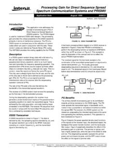
9 % Uc(n)=cos(theta(n)-4*pi/3);% end% Ua_ideal=cos(theta);%CASE3: voltageharmonics% for n=1:floor(L)% Ua(n)=cos(theta(n))+ *cos(5*theta(n));% Ub(n)=cos(theta(n)-2*pi/3)+ *(cos(5*(theta(n)-2*pi/3)));% Uc(n)=cos(theta(n)-4*pi/3)+ *(cos(5*(theta(n)-4*pi/3)));% end% Ua_ideal=cos(theta);% CASE4: voltagedipsand swellsfor n=1:floor(L/2)Ua(n)=cos(theta(n));Ub(n)= cos(theta(n)-2*pi/3);Uc(n)=cos(theta(n)- 4*pi/3);endfor n=floor(L/2):LUa(n)= *cos(theta(n));Ub(n)= *cos(theta(n)-2*pi/3);Uc(n)= *cos(theta(n)-4*pi/3);endBeloware the resultsof the varyinggrid conditionson the PLL:8 SoftwarePhaseLockedLoopDesignUsingC2000 MicrocontrollersforSPRABT4A November2013 ThreePhaseGrid ConnectedApplicationsSubmitDocumentation FeedbackCopyright 2013, ,Ub, AC ideal and Locked ,Ub, AC ideal and Locked ,Ub, AC ideal and Locked ,Ub, AC ideal and Locked (a)(c)(b)(d) 90 BVoltageImbalanceof 10%on one phaseC5% 5th HarmoniccontentDAmplitudechange(VoltageS agsand Dips)Figure4.
10 PLL Responseto VaryingGridConditions9 SPRABT4A November2013 SoftwarePhaseLockedLoopDesignUsingC2000 MicrocontrollersforThreePhaseGrid ConnectedApplicationsSubmitDocumentation FeedbackCopyright 2013, on C2000 ControllerUsingIQ MathAs the regularinvertertypicallyusesIQ24,and the Q pointchosenfor the PLL is IQ21as shownin theabovesection, the codefor the PLL can be writtenas :#ifndefSPLL_3ph_SRF_IQ_H_#defineSPLL_3p h_SRF_IQ_H_#defineSPLL_SRF_Q_IQ21#define SPLL_SRF_Qmpy_IQ21mpy//**StructureDefini tion**//typedefstruct{int32B1_lf;int32B0 _lf;int32A1_lf;}SPLL_3ph_SRF_IQ_LPF_COEF F;typedefstruct{int32v_q[2];int32ylf[2]; int32fo; // outputfrequencyof PLLint32fn; //nominalfrequencyint32theta[2];int32del ta_T;SPLL_3ph_SRF_IQ_LPF_COEFFlpf_coeff; }SPLL_3ph_SRF_IQ;//**FunctionDeclaration s**//voidSPLL_3ph_SRF_IQ_init(intGrid_fr eq,longDELTA_T,SPLL_3ph_SRF_IQ*spll);voi dSPLL_3ph_SRF_IQ_FUNC(SPLL_3ph_SRF_IQ*sp ll_obj);//**MacroDefinition**//#defineSP LL_3ph_SRF_IQ_MACRO(spll_obj)\/*updat