Transcription of Specifications - Installation and Operating Instructions
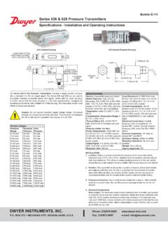
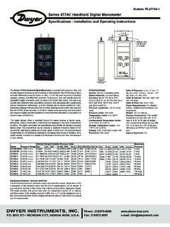
1 Model FS-2 Paddle Flow SwitchSpecifications - Installation and Operating InstructionsBulletin W-002 SPECIFICATIONSS ervice: Compatible liquids. Wetted Materials: Bellow: Tin-bronze;Vane: Stainless Steel;Body: Forged Limit: 230 F (110 C).Pressure Limit: 145 psig (10 bar).Enclosure Rating: Type: SPDT snap Rating: 10A res, 3A ind @ 250 Connection: Cable gland with attached wire Connection: 1 male Orientation: Switch must be installed vertically on horizontal Point Adjustment: Four vane combinations and an adjustment : Die-cast aluminum : oz ( kg).
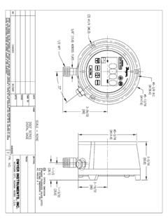
2 Agency ConnectionsConnect wire leads in accordance with local electrical codes and switch actionrequired. contact will close and contact will open when flow increases tothe actuation point. They will return to normal condition when flow decreases tothe deactuation point. Brown = Common, Blue = Normally Open, Black = NormallyClosed, and Yellow/Green = Earth [ ]5-1 [77]5-49/64[ ]XThe Model FS-2 Paddle Flow Switchoffers an economical flow proving set points tailored for the application are enabled by field adjustable vanelayers and a set point adjustment screw.
3 The FS-2 features an aluminumweatherproof housing for outdoor Installation . Paddles are adjustable to fit 1 to 8 size pipe. FS-2 is ideal for use in flow or no flow applications in cold and hotwater Field Adjustable Paddle Field Adjustable Set Point Weatherproof ConstructionINSTALLATIONU npack and remove any packing material found in the lower housing. Install inpiping with the arrow pointing in the direction of flow. The switch must be installedvertically on horizontal pipe runs. To ensure a steady working flow, make certain tokeep the paddle flow switch a safe distance from sources of turbulence such aselbows, valves, pumps, etc.
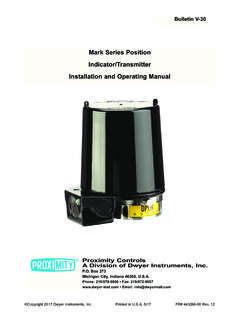
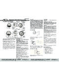
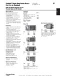
4 The recommended minimum distance upstream anddownstream of the flow switch is about 5 times the pipe s : When installed, make sure that the vane has full range of motion and is nothindered by contacting the wall of a pipe, bushing, or 1 Phone: 219 : 219/872-9057e-mail: ANDERSON DIV., DWYER INSTRUMENTS, BOX 358 MICHIGAN CITY, INDIANA 46360 A. Copyright 2014 Dwyer Instruments, in 9/14FR# R5-443380-00 Rev. 1 Once you have the correct vane length, you can then adjust the flow rate settingby means of the adjustable bolt shown in Figure 2. Fully tighten the adjustable boltto obtain the minimum flow rate setting.
5 Fully loosen the adjustable bolt to obtainthe maximum flow rate setting. The adjustable bolt can be adjusted and setaccording to practical requirements. See Table 1 for the limiting flow rate settingsin relation to the pipe diameter and blade : The Model FS-2 is shipped with the adjustable bolt fully tightened, in theminimum setting. Also, the pre-set bolt shown in Figure 2 has been adjusted beforeleaving the factory. Users should not adjust this by themselves. Adjustment of thepre-set bolt could lead to switch malfunction and possibly void the warranty.
6 Figure 2: AdjustmentMAINTENANCEI nspect and clean wetted parts at regular intervals. The cover should be in place atall times to protect the internal components from dirt, dust, and the device from the supply circuit before opening to prevent ignition ofhazardous Model FS-2 Paddle Flow Switch is not field serviceable and should be returnedif repair is needed (field repair should not be attempted and may void warranty). Besure to include a brief description of the problem plus any relevant applicationnotes. Contact customer service to receive a return goods authorization numberbefore OF FLOW RATE SETTINGD etermine the correct blade length, which is based on the size of your pipe (seeTable 1).
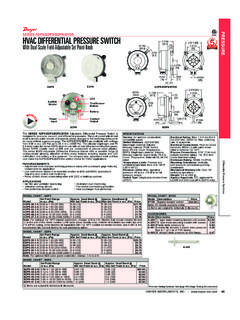
7 Remove only those layers which are too long. Leave the smaller layerson to reinforce the vane. To remove vane layers, proceed as follows:a. Remove the screw and lockwasher holding the layers together. Do not lose these Remove the unwanted Resecure the vane with the original screw and With a hammer, lightly peen the end of the screw so that it can not back If you lose the screw or lockwasher, do not replace with other parts which may corrode and break. That will void the warranty and might cause severe damage to equipment located downstream of the (inch)11-1/41-1/222-1/234568 Blade Lengthin (mm)Dim.
8 (34) (34) (57) (57) (88) (88) (88) (167) (167) (167)Approximate Actuation and DeactuationFlow Rates for WaterMinimum SettingGPM (LPM)Maximum SettingGPM (LPM) ( ) ( ) ( ) ( ) ( ) ( ) ( ) ( ) ( ) ( ) ( ) ( ) ( ) ( ) ( ) ( ) ( ) ( ) ( ) ( ) ( ) ( ) ( ) ( ) ( ) ( ) ( ) ( ) ( ) ( ) ( ) ( ) ( ) ( ) ( ) ( ) ( ) ( ) ( ) ( )TABLE 1: FLOW RATE CHARTP hone: 219 : 219/872-9057e-mail: ANDERSON DIV., DWYER INSTRUMENTS, BOX 358 MICHIGAN CITY, INDIANA 46360 A.