Transcription of Specifications - Installation and Operating Instructions
1 Series A3000 Photohelic Differential Pressure Switch/GageSpecifications - Installation and Operating InstructionsBulletin B-33-AThe SERIES A3000 PHOTOHELIC Switch/Gage is a versatile 2-in-1 instrument combining a time-proven Magnehelic differential pressure gage with low/high pressure switches. It is designed to measure and control positive, negative or differential pressure of air or other non-combustible, non-corrosive gases. Gage reading is unaffected by switch operation. Switch set points are easily adjusted with knobs located on gage face. Applied pressure and switch set points are fully visible at all times. Deadband is one pointer width, less than 1% of full scale. Each set point controls a DPDT relay and both relays can be interlocked to provide variable deadband Location: Select a clean, dry, vibration-free location where ambient temperatures will be between 20 and 120 F ( and C). Tubing supplying pressure to the instrument can be practically any length but long runs will increase response time Position: The PHOTOHELIC Switch/Gage is factory calibrated for use with scale in a vertical plane.
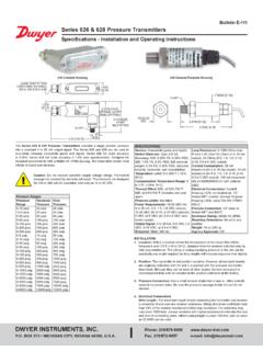
2 Operation at other angles may affect accuracy and/or require zero adjustment. Most models can be specially calibrated at the factory for other positions if specified at time of ordering. Ranges below 1 in must be used only with scale Mounting: The PHOTOHELIC Switch/Gage is normally mounted before making electrical connections. The electrical enclosure is removable at any time regardless of mounting method.(A) Panel Mounting: Normal mounting is flush or through panel as shown in Figure B. Allow 4-3/8 ( mm) clearance behind the unit for removal of electrical enclosure. Make a 4-13/16 ( mm) diameter hole in panel. Insert the PHOTOHELIC Switch/Gage unit from front of panel and slip mounting ring over case from behind with stepped side facing rear. Fit the snap ring into narrow groove at back edge of the bezel. Thread four 6-32 x 1-1/4 mounting screws into tapped holes in mounting ring and seat it against snap ring.
3 Tighten screws against back of panel. See Figure SPECIFICATIONSS ervice: Air and non-combustible, compatible Materials: Consult : 2% of full scale at 70 F ( C). 3% on -0 and 4% on -00 models. Pressure Limits: -20 Hg. to 25 psig ( to bar). MP option; 35 psig ( bar), HP option; 80 psig ( bar). 36003S 36010S; 150 psig ( bar). 36020S and higher; x full scale pressure. Temperature Limits: 20 to 120 F ( to C) Low temperature option available. Process Connections: 1/8 female NPT. Size: 4 ( mm) dial face, 5 (127 mm) x 8-1/4 ( mm).Weight: 4 lb ( kg). SWITCH SPECIFICATIONSS witch Type: Each setpoint has 2 Form C relays (DPDT).Repeatability: 1% of full Rating: 10A @ 28 VDC, 10A @ 120, 240 VAC. Electrical Connections: Screw terminals. Use 167 F (75 C) copper conductors Requirements: 120 VAC, 50/60 Hz; 240 VAC & 24 VAC Power Orientation: Diaphragm in vertical position. Consult factory for other position Point Adjustment: Adjustable knobs on face.
4 Agency Approvals: CE, CSA, [ ]2-1/16 [ ]2 [ ]1-1/4[ ](4) 6-32 HOLESEQUALLY SPACED ONA 5-1/8 [ ] 4-47/64[ ] 5[ ] 4 [ ]FACE5-1/2 [ ] RING5/8 [ ]5/8 [ ]PANEL MAX3/16 [ ]3-7/8 [ ]5-1/8 [ ]6-3/8 [ ]7-5/8 [ ]4-3/8 [ ]HOUSING REMOVAL3/4 CONDUITCONNECTION 4-3/4[ ]3-7/8 SQ[ ]1/8 FEMALE NPT HIGHPRESSURE CONNECTION1/8 FEMALE NPT LOWPRESSURE CONNECTIONNote: Detailed dimension drawings are available from our Customer Service Dept. for PHOTOHELIC switch/gages as installed in two optional enclosures. For weatherproof housing, request no. 13-700132-00. /For explosion-proof housing, request no. A 4-13/16 [ ]HOLE REQUIRED FORPANEL MOUNTING1/2 NPT(M) PRESSURE HIGH PRESSURE CONNECTIONFOR SERIES 36000S RING GROOVEF igure B DWYER INSTRUMENTS, BOX 373 MICHIGAN CITY, INDIANA 46360, : 219/879-8000 Fax: 219 : Surface Mounting with Remote Relays: Where it is preferred to mount the amplifier-relay unit separate from the gage assembly, the gage is mounted as shown in Figure B (without amplifier-relay package) or surface mounted as shown in Figure C.
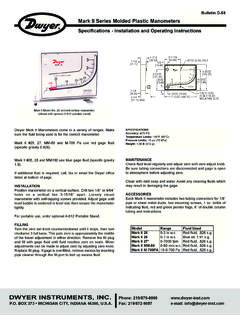
5 Use the dimensions in Figure D to locate holes.(C) Remote Relays Mounting: On factory supplied RMR (remote mounted relay) units, the amplifier-relay package will be furnished attached to a mounting plate as shown in Figure E. Use the hole layout in Figure F for this option. A five foot cable assembly is included for connecting the two components. Longer cable lengths are available from the factory.(D) Type 2 Environment Installation Requirements: When installing in an indoor location where the amplifier-relay unit is exposed to falling or dripping water, a drain opening must be drilled in the bottom of the amplifier-relay enclosure. Drill the opening as shown in Figure Pneumatic Connections & Zeroing: After Installation but before making pressure connections, set the indicating pointer exactly on the zero mark, using the zero adjust screw located at the bottom of the front cover. Note that this adjustment can only be made with the high and low pressure taps both open to the high and low pressure taps to positive, negative, or differential pressure sensing points.
6 Use 1/4 diameter metal or other instrument tubing and 1/8 NPT adapters at the PHOTOHELIC pressure switch/gage. Adapters for rubber or soft plastic tubing are furnished with the instrument for use where this type of connection is the PHOTOHELIC Switch/Gage is not used to sense differential pressure, one of the pressure taps must be left open to atmosphere. This will allow the reference pressure to enter. In this case, Installation of a Dwyer Instruments, Inc. No. A-331 Filter Vent Plug or similar fitting in the reference pressure tap is recommended to reduce the possibility of dust entering the : If the PHOTOHELIC switch/gage is over pressured, pointer may jump from full scale back to zero and remain there until the excess pressure condition is relieved. Users should be aware of possible false zero pressure indications under this MAXIMUM 1/8" ( )DIAMETER THRU HOLE IN THIS AREA FOR CFigure FFigure E(3) 3/16 [ ] MOUNTINGHOLES EQUALLY SPACED ON A 401/8 [ ] 3/4 [ ] WIRECONNECTION HOLE1-1/8[ ]1-1/8[ ]Figure DFigure G 3/16 TYP 4 PLACES4-9/32[ ]4-9/32[ ]5[ ] SQELECTRICAL CONNECTIONS1.
7 Cover: The amplifier-relay unit has an easy to remove housing. Remove the three (3) screws as shown in Figure H and slide the housing off. Make all the electrical connections before reinstalling and refastening the Conduit: Electrical access to the connection box portion of the relay housing is by bottom opening for 3/4 conduit. Use of flexible conduit is recommended. It should be supported from the panel or other suitable surface to prevent the wiring system from exerting undue strain on the instrument. See Figure Terminal or Connection Board Layout: In Figure J Terminal Board, Section A contains the connections for the load or slave relay actuated by the high or right set point. This relay is a double pole, double throw type. The two right connections are normally closed, the two middle connections are normally open, and the left connections are the common pair. The relay is in its normal or De-Energized position when pressure is below the right hand set D is exactly the same as Section A except that its load or slave relay is controlled by the low or left set point.
8 The De-Energized position is below the left hand pointer set B contains the external connections to the holding coil circuit for the high or right set point relay and Section C contains similar connections for the low or left set point relay. The function and use of these connections varies somewhat depending on the circuit style of the instrument. See paragraphs 5 and 6 for details. Section E contains the power connections for the control unit transformer primary. The transformer in turn supplies reduced voltage power for the LED, phototransistor, amplifier unit, and load relay pull in and hold coils. Connections must always be made to this section in order to put the unit in operation. Standard units are designed for 120 VAC input to the transformer. Special units are also available for other Ground Wire attachment is provided for by a No. 6-32 screw on the mounting bracket near the conduit opening.
9 An additional ground wire connection is located on the side of the gage body for use when the amplifier-relay unit is mounted Set Point instruments are furnished with the right or high set point components and circuitry in place. These are connected to Sections A and B of the terminal board. The left or low set point components are Circuit Style: The PHOTOHELIC SWITCH/GAGE is available with several factory installed optional internal circuits. They are identified as to style by a label shown in Figure K. This label is mounted prominently on the terminal board of each instrument. The letter H denotes a circuit in which the relay can be made to latch or remain energized after pressure increase to its set letter L denotes a circuit in which the relay can be made to latch or remain de-energized after pressure decrease to its set point. Two letters are required to fully identify a dual set point unit. Thus, circuit style HH, which is standard, is a dual set point circuit which has provisions for latching on pressure increase to either set point.
10 Single relay unit or L for the special low latch unit. Units for use with other than standard 120 VAC will be so indicated on the Dual Set Point Automatic Reset: Circuit Style HH is used for simple on-off switching applications. To place in service, connect load circuits to the appropriate terminals in Section A (Figure J) for the right set point and Section D for the left set point. Note that the contacts are open when the gage pressure pointer is to the left of the set point pointers. No connections are necessary in Sections B and C. Make external ground connections as required and connect power to Section E for the control unit. To use circuit style LL for automatic reset, a jumper wire must be installed between the two terminals in Sections B and/or C. 6. Dual Set Point Manual Reset: Circuit Style HH may also be used for manual reset applications where it is required to maintain contact on either relay following pressure increase above its set point.