Transcription of STMPS2141, STMPS2151, STMPS2161, STMPS2171
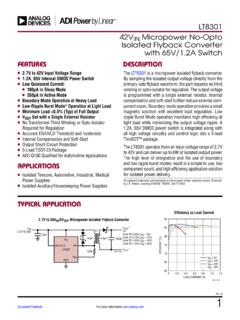
1 This is information on a product in full production. February 2022 DocID013793 Rev 71/39 STMPS2141, STMPS2151, STMPS2161, STMPS2171 Enhanced single channel power switchesDatasheet - production dataFeatures 90 mW high-side MOSFET switch 500/1000 mA continuous current Thermal and short-circuit protection with overcurrent logic output Operating range from to V CMOS and TTL compatible enable input undervoltage lockout (UVLO) 12 A maximum standby supply current Ambient temperature range, -40 to 85 C ESD protection: 8 kV HBM Reverse current protection Fault blanking UL recognized components (UL file number: E354278)DescriptionThe STMPS2141, STMPS2151, STMPS2161, STMPS2171 power distribution switches are intended for applications where heavy capacitive loads and short-circuits are likely to be encountered.
2 These devices incorporate 90 mW N-channel MOSFET high-side power switches for power distribution. These switches are controlled by a logic enable the output load exceeds the current limit threshold or a short is present, the device limits the output current to a safe level by switching into a constant current mode. When continuous heavy overloads and short-circuits increase the power dissipation in the switch, causing the junction temperature to rise, a thermal protection circuit shuts the switch off to prevent damage. Recovery from a thermal shutdown is automatic once the device has cooled sufficiently. Internal circuitry ensures the switch remains off until a valid input voltage is present.
3 SOT23-5 LSO-8 MSOP8 Table 1. Device summaryOrder codesRated continuous output current(mA)EnableSO-8 SOT23-5 LMSOP8(1)STMPS2141 MTRSTMPS2141 STRSTMPS2141 TTR500 Active lowSTMPS2151 MTRSTMPS2151 STRSTMPS2151 TTR500 Active highSTMPS2161 MTRSTMPS2161 STRSTMPS2161 TTR1000 Active lowSTMPS2171 MTRSTMPS2171 STRSTMPS2171 TTR1000 Active high1. MSOP8 package is also known as TSSOP8 . , STMPS2151, STMPS2161, STMPS21712/39 DocID013793 Rev 7 Contents1 Block diagram .. 72 Pin settings .. connections .. description .. 83 Functional description .. blanking .. protection .. conditions .. current blocking.
4 104 Ambient temperature .. 115 Maximum ratings .. maximum ratings .. operating conditions .. 126 Electrical specifications .. 137 Detail device characteristics .. , STMPS2151 additional electrical charts .. characteristics at VOUT = V .. characteristics at VOUT= V .. protection characteristics .. electrical characteristics .. , STMPS2171 electrical charts .. characteristics at VOUT = V .. characteristics at VOUT= V .. protection characteristics .. electrical characteristics .. 26 DocID013793 Rev 73/39 STMPS2141, STMPS2151, STMPS2161, STMPS2171 Contents398 Package mechanical data.
5 299 Ordering information .. 3710 Revision history .. 38 List of tablesSTMPS2141, STMPS2151, STMPS2161, STMPS21714/39 DocID013793 Rev 7 List of tablesTable summary .. 1 Table description .. 7 Table conditions.. 8 Table (191 C/W) .. 10 Table (220 C/W) .. 10 Table (160 C/W).. 10 Table maximum ratings .. 11 Table operating conditions .. 11 Table electrical characteristics .. 12 Table electrical characteristics.. 12 Table limit characteristics (VIN= V, IOUT= rated current, TJ= 25 C, unless otherwise specified) .. 13 Table current characteristics (VIN= V, IOUT= rated current, TJ= 25 C, unless otherwise specified).
6 13 Table characteristics (VIN= V, IOUT= rated current, TJ= 25 C, unless otherwise specified) .. 14 Table characteristics (VIN= V, IOUT= rated current, TJ= 25 C, unless otherwise specified) .. 14 Table pin characteristics (VIN= V, IOUT= rated current, TJ= 25 C, unless otherwise specified) .. 14 Table pin characteristics(VIN= V, IOUT= rated current, TJ= 25 C, unless otherwise specified) .. 14 Table package mechanical data .. 28 Table footprint dimensions .. 29 Table mechanical data .. 31 Table package mechanical data .. 33 Table mechanical data .. 35 Table codes .. 36 Table revision history.
7 37 DocID013793 Rev 75/39 STMPS2141, STMPS2151, STMPS2161, STMPS2171 List of figures39 List of figuresFigure diagram .. 7 Figure , SO-8 and MSOP8 pin connections .. 8 Figure output turn-on delay time (STMPS2141/2151, 5 V).. 17 Figure output turn-off delay time (STMPS2141/2151, 5 V).. 17 Figure output turn-on delay time (STMPS2141/2151, 5 V) .. 17 Figure output turn-off delay time (STMPS2141/2151, 5 V) .. 17 Figure output turn-on delay time (STMPS2141/2151, 3 V).. 18 Figure output turn-off delay time (STMPS2141/2151, 3 V).. 18 Figure output turn-on delay time (STMPS2141/2151, 3 V) .. 18 Figure output turn-off delay time (STMPS2141/2151, 3 V).
8 18 Figure rising (STMPS2141/2151) .. 19 Figure falling (STMPS2141/2151) .. 19 Figure protection at VOUT = V (STMPS2141/2151) .. 19 Figure protection at VOUT = V (STMPS2141/2151 - details) .. 19 Figure 17. ICC vs. VIN (enabled) (STMPS2141/2151) .. 20 Figure vs. temperature (enabled) (STMPS2141/2151) .. 20 Figure protection at VOUT = V (STMPS2141/2151) .. 20 Figure protection at VOUT = V (STMPS2141/2151 - details) .. 20 Figure vs. VIN (disabled) (STMPS2141/2151) .. 20 Figure vs. temperature (disabled) (STMPS2141/2151) .. 20 Figure vs. VIN (STMPS2141/2151) .. 21 Figure vs. temperature (STMPS2141/2151).
9 21 Figure vs. temperature (STMPS2141/2151) .. 21 Figure leakage vs. temperature (STMPS2141/2151) .. 21 Figure rise time vs. VIN (STMPS2141/2151) .. 21 Figure 26. Output fall time vs. VIN (STMPS2141/2151) .. 21 Figure vs. temperature (STMPS2141/2151) .. 22 Figure 28. Voltage output turn-on delay time (STMPS2161/2171, 5 V) .. 23 Figure output turn-off delay time (STMPS2161/2171, 5 V).. 23 Figure 30. Current output turn-on delay time (STMPS2161/2171, 5 V) .. 23 Figure 31. Current output turn-off delay time (STMPS2161/2171, 5 V) .. 23 Figure 32. Voltage output turn-on delay time (STMPS2161/2171, 3 V).
10 24 Figure 33. Voltage output turn-off delay time (STMPS2161/2171, 3 V) .. 24 Figure 34. Current output turn-on delay time (STMPS2161/2171, 3 V) .. 24 Figure 35. Current output turn-off delay time (STMPS2161/2171, 3 V) .. 24 Figure rising (STMPS2161/2171) .. 25 Figure 37. UVLO falling (STMPS2161/2171) .. 25 Figure 38. OC protection at VOUT = V (STMPS2161/2171) .. 25 Figure 39. OC protection at VOUT = V (STMPS2161/2171- detail) .. 25 Figure 42. ICC vs. VIN (enabled) (STMPS2161/2171) .. 26 Figure 43. ICC vs. temperature (enabled) (STMPS2161/2171).. 26 Figure 40. OC protection at VOUT = V (STMPS2161/2171).